
Conditioning and/or heating plant and process of controlling the same plant

a technology of heating plant and process, which is applied in the direction of heating types, lighting and heating apparatus, instruments, etc., can solve the problems of inability to manage the plant in order to optimize energy consumption, complicated control of the conditioning and/or heating plant, and the initial condition of the plan

Active Publication Date: 2019-10-15
FIMCIM SPA
View PDF26 Cites 0 Cited by
  • Summary
  • Abstract
  • Description
  • Claims
  • Application Information

AI Technical Summary

Benefits of technology

The invention is about a system for controlling and conditioning buildings. It includes a system for managing energy usage in multiple separate environments, such as a control process for a heating system. The system can also have a valve to manage the flow of fluids in the system. The technical effect of this invention is to improve the energy efficiency of conditioning and heating systems for multiple environments.

Problems solved by technology

Controlling the conditioning and / or heating plants is somewhat complicated particularly when there are many environments supplied by the same plant, which therefore is provided with many heat exchange units: in this regard, let's consider plants destined to offices, hotels, or generally complexes wherein there are many separated environments.
It is clear that setting the initial condition of the plant and controlling the compliance with a desired thermal condition in each environment is extremely complicated.
However, the solution illustrated in the patent application WO2010074921A2 is not capable of managing the plant in order to optimize the energy consumptions.
Moreover, such known solution does not lend itself neither to control in real-time the user energy exchange modes, nor to take the flow resistances of the distributing system into account, nor to optimize such resistances.

Method used


Image

  • Conditioning and/or heating plant and process of controlling the same plant
  • Conditioning and/or heating plant and process of controlling the same plant
  • Conditioning and/or heating plant and process of controlling the same plant

Examples


Embodiment Construction

[0318]Conditioning and / or Heating Plant

[0319]With reference to the attached figures, 1 generally indicates a conditioning and / or heating plant for example useable both in the civilian field and in the industrial one and advantageously exploitable, in a non limiting way, for controlling and optimizing hydronic plants.

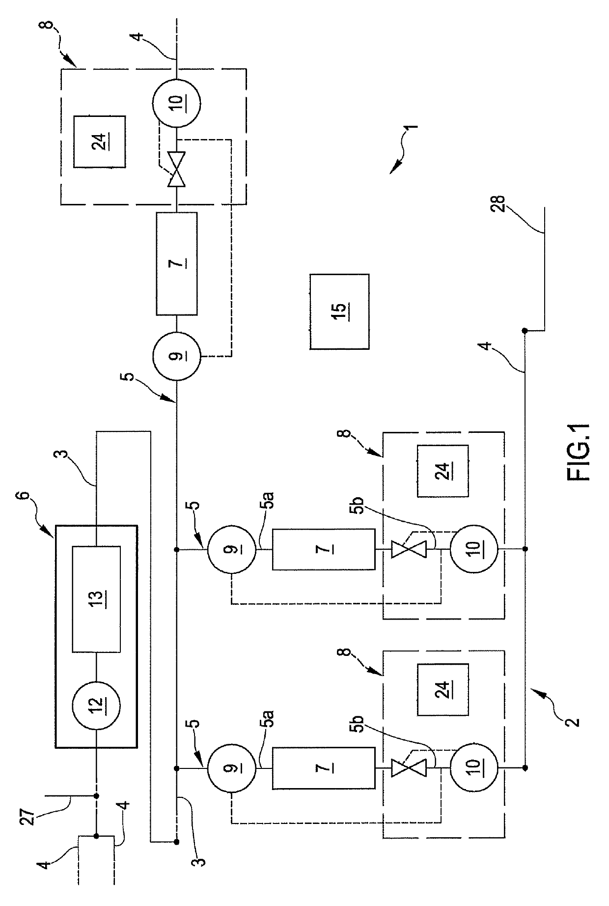
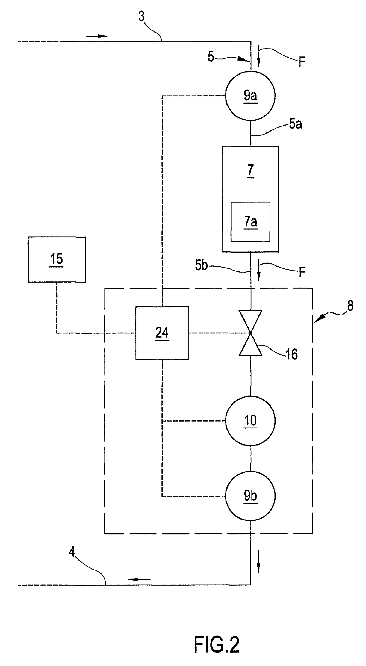
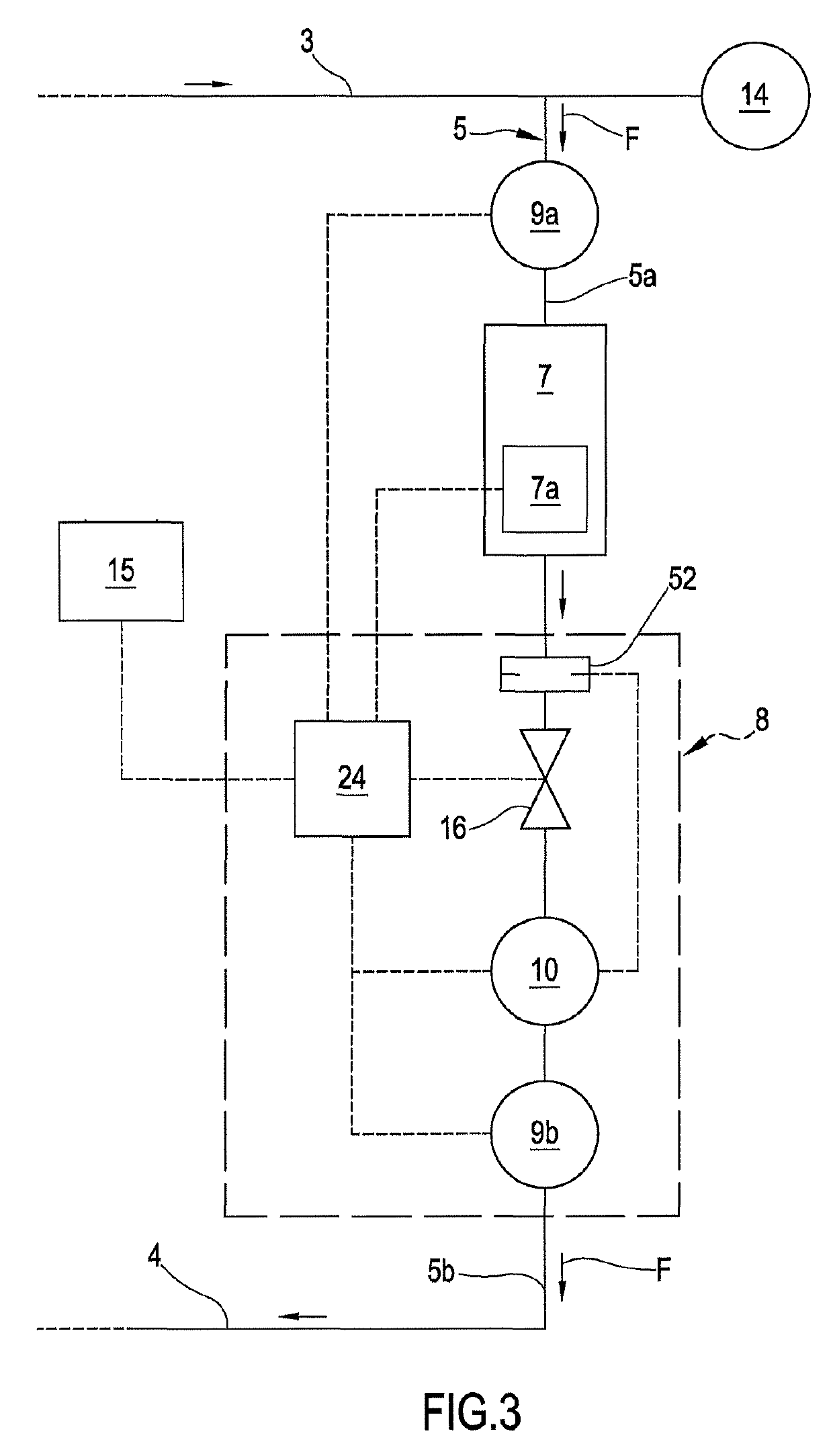
[0320]As it is for example visible in FIG. 1, the plant 1 comprises a circuit 2 for distributing a carrier fluid; the circuit 2 exhibits at least two main channels, in other words: a delivery line 3 for delivering the carrier fluid to a predetermined number of heat exchange users or units 7 and a return line 4 fluidically communicating with the delivery line 3 and arranged for receiving the carrier fluid downstream each of said units 7. As it is visible in FIG. 1, the distributing circuit comprises a plurality of circulating channels or distributing branches (in the following will be indicated by the term channels) 5 directly or indirectly connected to the delivery line ...


PUM


Abstract

A conditioning or heating plant and a process of controlling the plant, wherein plant comprises at least one circuit for distributing a carrier fluid, having a delivery line, a return line, and a plurality of channels directly or indirectly connected to the delivery line and return line and configured for supplying respective environments to be conditioned and / or heated, at least one heat treatment central group placed on the circuit. The plant has, for each of the channels, at least one respective heat exchange unit and at least one flow-rate regulator.

Description

CROSS REFERENCE TO RELATED APPLICATIONS[0001]This application claims priority to Italian patent application number 102015000050079, entitled “Conditioning and / or Heating Plant and Process of Controlling the Same Plant,” filed Sep. 9, 2015, the contents of which are herein incorporated by reference in its entirety.FIELD OF THE INVENTION[0002]The present invention refers to a conditioning and / or heating plant and a process of controlling the same plant. The invention is useable both in the civilian and in the industrial fields, and advantageously is exploitable for controlling and optimizing hydronic-type plants from the energy point of view.STATE OF THE ART[0003]As it is known, the heating and / or conditioning plants are increasingly used for maintaining environments, such as rooms destined to the residential or work use, at desired temperature and / or humidity conditions.[0004]Generally, such plants are supplied by a central unit, for example comprising a heating unit (such as a boile...

Claims


Application Information

Patent Timeline
Patent Type & Authority Patents(United States)
IPC IPC(8): F24D19/10F16K37/00G05D7/06G05D23/19F24F11/83F24D3/02F24F11/85F24F11/84F24D10/00F16K5/04F24D3/10
CPCF24D3/10F24D19/1036F24D2220/0264F24D2220/0271F24D2220/0292F24D2220/042F24D2220/044F24D2220/046G05D7/0635G05D23/1924G05D23/1928F24F11/83F24F11/84F24F11/85F16K37/0041F16K37/005F16K5/04Y02B30/17F24D3/02F24D10/00F24D19/1012F24D19/1015F24D19/1048Y02B30/70F16K37/00
Inventor GUIDETTI, TIZIANOCHIARELLO, ANDREACERUTTI, ALFREDOCIMBERIO, ROBERTOCIMBERIO, RENZO
Owner FIMCIM SPA
Learn More