Battery pack

a battery pack and battery technology, applied in the field of batteries, can solve the problems of shock transmission to a plurality of cell stacks housed in the housing case, the difficulty of sufficiently suppressing collision between the rear suspension and the housing case, and the breakage of cell stacks, etc., and achieve the effect of suppressing the mutual interference of the lower-side cell stacks moving to come closer to each other

Active Publication Date: 2020-03-24
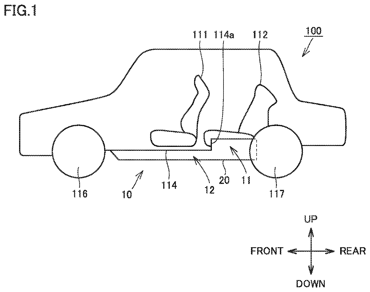
TOYOTA JIDOSHA KK
View PDF6 Cites 0 Cited by
  • Summary
  • Abstract
  • Description
  • Claims
  • Application Information

AI Technical Summary

Benefits of technology

[0009]The present disclosure has been made in light of the above-described problem, and an object of the present disclosure is to provide a battery pack that makes it possible to suppress a break of a plurality of cell stacks housed in a housing case.
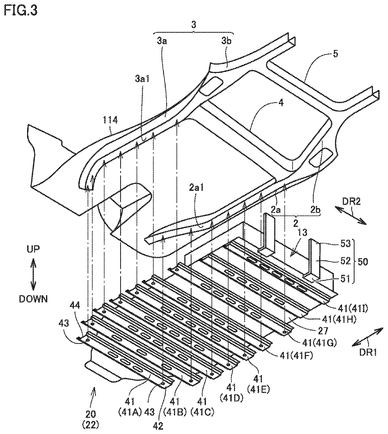
[0013]The shock is distributed by the support member as described above, and thus, direct provision of the shock to the plurality of cell stacks housed in the housing case can be suppressed. As a result, a break of the plurality of cell stacks housed in the housing case can be suppressed.
[0016]In the battery pack configured as described above, the up-down-direction distance between the second cell stacks arranged on the second housing region side located on the rear side of the vehicle and the upper wall portion is longer than the up-down-direction distance between the first cell stacks arranged on the first housing region side located on the front side of the vehicle and on one side in the first direction and the upper wall portion. Therefore, in the valley-folded portion of the housing case, a space that allows movement of the cell stacks can be sufficiently ensured, and mutual interference of the cell stacks moving to come closer to each other can be suppressed. As a result, collision between the cell stacks can be suppressed.
[0020]Therefore, a space between the one-side ends of the at least one or more upper-side cell stacks located on the one side in the first direction and the front wall portion can be sufficiently ensured. As a result, even when the front wall portion collides with the cross member located on the front side of the front wall portion and is deformed, interference of the upper-side cell stacks with the front wall portion can be suppressed.
[0022]In such a configuration, when the housing case is deformed in a valley-folded manner in a portion located between the lower-side cell stacks arranged below the upper-side cell stacks facing the front wall portion and the lower-side cell stacks located on the front side (one side in the first direction) of the above-described lower-side cell stacks, a space that allows movement of the lower-side cell stacks adjacent to each other can be more sufficiently ensured in the valley-folded portion of the housing case. As a result, mutual interference of the lower-side cell stacks moving to come closer to each other can be suppressed.

Problems solved by technology

In such a case, the bracket disclosed in Japanese Patent Laying-Open No. 2011-218910 has difficulty in sufficiently suppressing collision between the rear suspension and the housing case.
When the rear suspension collides with the housing case, it is concerned that shock is transmitted to a plurality of cell stacks housed in the housing case.
In this case, the cell stacks may be broken in some cases.

Method used


Image

  • Battery pack
  • Battery pack
  • Battery pack

Examples


case 22

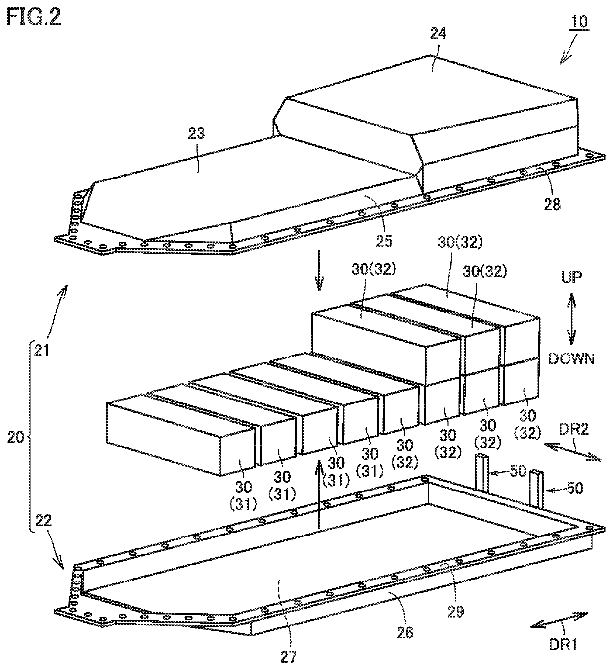
[0038]Lower case 22 has a box shape that is open upwardly. Lower case 22 has bottom portion 27 described above, a sidewall portion 26 and a flange portion 29. Bottom portion 27 is provided to face ceiling portion 23 in the up-down direction. Sidewall portion 26 is provided to extend upwardly from an outer peripheral edge of bottom portion 27. Sidewall portion 26 forms a sidewall of housing case 20, together with sidewall portion 25 of upper case 21. Flange portion 29 extends from an upper end of sidewall portion 26 to the outside of housing case 20, thereby forming a flange shape.

[0039]With flange portion 28 and flange portion 29 being stacked in the up-down direction, flange portion 28 and flange portion 29 are fastened by a plurality of fastening members (not shown). As a result, upper case 21 and lower case 22 are integrally coupled to each other and form a space for housing the plurality of cell stacks 30.

[0040]The plurality of cell stacks 30 include a plurality of first cell st...


PUM

PropertyMeasurementUnit
widthaaaaaaaaaa
heightaaaaaaaaaa
distanceaaaaaaaaaa

Abstract

A battery pack includes: a plurality of cell stacks; a housing case configured to house the plurality of cell stacks; and a support member configured to allow a rear cross member provided in a vehicle to support the housing case, the housing case including a rear portion directed to a rear side of the vehicle in a mounted state in which the battery pack is mounted on the vehicle, the support member extending in an up-down direction and being fixed to the housing case from an outer side of the housing case so as to face the rear portion.

Description

[0001]This nonprovisional application is based on Japanese Patent Application No. 2018-054793 filed on Mar. 22, 2018 with the Japan Patent Office, the entire contents of which are hereby incorporated by reference.BACKGROUNDField[0002]The present disclosure relates to a battery pack, and particularly to a battery pack mounted on a vehicle.Description of the Background Art[0003]A battery pack configured to supply electric power to a motor is mounted on a vehicle such as an electric vehicle and a hybrid vehicle. The battery pack is assembled at a position located forward of a rear suspension, and below a floor panel of the vehicle.[0004]For example, Japanese Patent Laying-Open No. 2011-218910 discloses a vehicle having a battery pack mounted thereon.[0005]In the vehicle disclosed in Japanese Patent Laying-Open No. 2011-218910, a bracket fixed to a side member is provided with a case mount portion configured to support a battery pack case (housing case), and a suspension mount portion c...

Claims


Application Information

Patent Timeline
Patent Type & Authority Patents(United States)
IPC IPC(8): H01M2/10B60L50/60B60L50/64
CPCB60L50/64H01M2/1077H01M2/1083B60L50/66H01M2220/20B60K1/04B60K2001/0405H01M50/204H01M50/249B60L3/0007
Inventor WATANABE, HIROTAKAINOUE, SHIGEYUKIINUKAI, SATOSHIMIZUNO, TERUCHIKA
Owner TOYOTA JIDOSHA KK
Why Eureka
Try Eureka