Cable fixing structure

Active Publication Date: 2018-04-19
HONDA MOTOR CO LTD
View PDF4 Cites 0 Cited by
  • Summary
  • Abstract
  • Description
  • Claims
  • Application Information

AI Technical Summary

Benefits of technology

[0016]In the present invention, the flat cable is pressed by the heat contraction tube against the convexly curved surface. Therefore, when a pulling force in a longitudinal direction is applied to the flat cable, it

Problems solved by technology

However, in the conventional technique like Japanese Laid-Open Patent Publication No. 2009-266474, since the flat cable is sandwiched and held in the thickness direction, between the flat plate cable holders, when a pulling force is applied to the flat cable in a longitudina

Method used


Image

  • Cable fixing structure
  • Cable fixing structure
  • Cable fixing structure

Examples


Embodiment Construction

[0025]Hereinafter, a preferred embodiment of a cable fixing structure according to the present invention will be described in relation to a fuel cell system, with reference to the accompanying drawings.

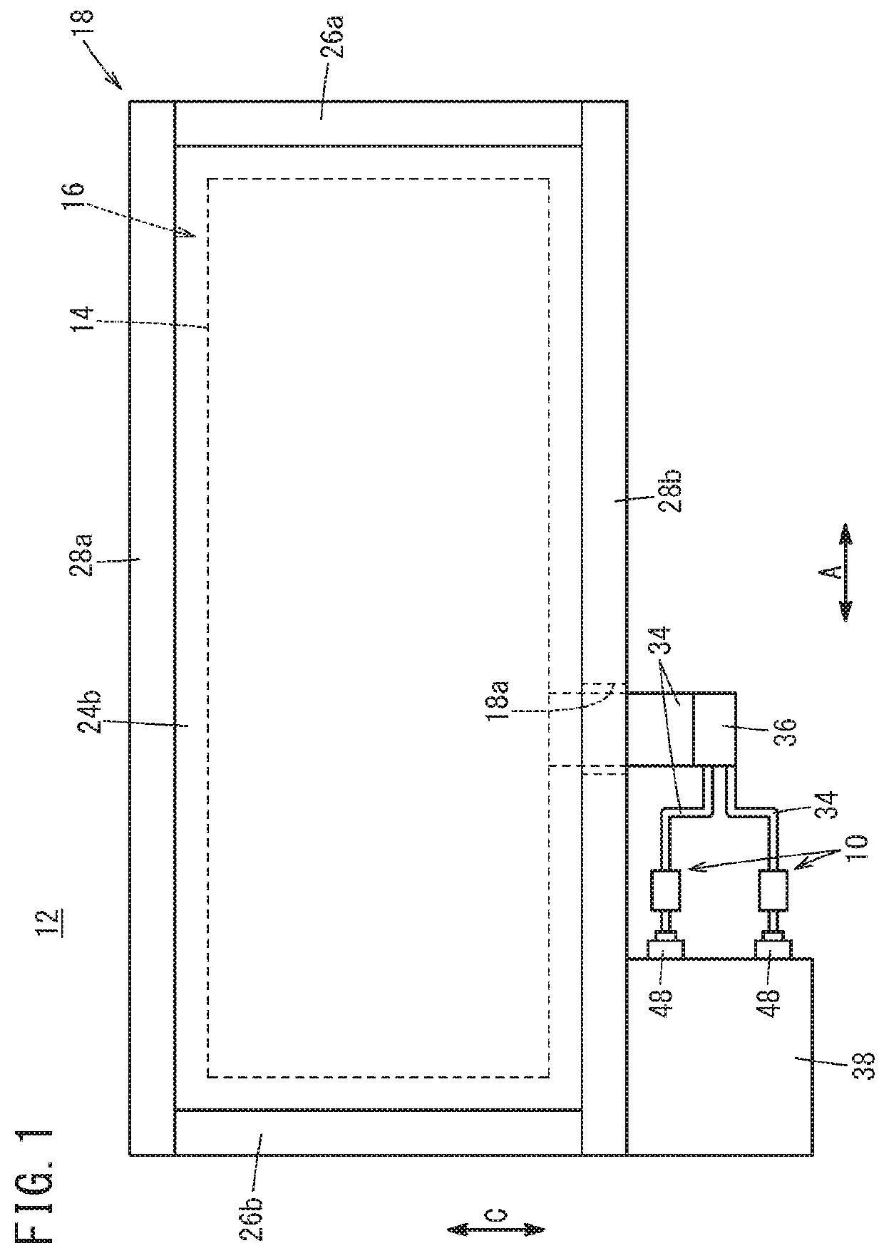
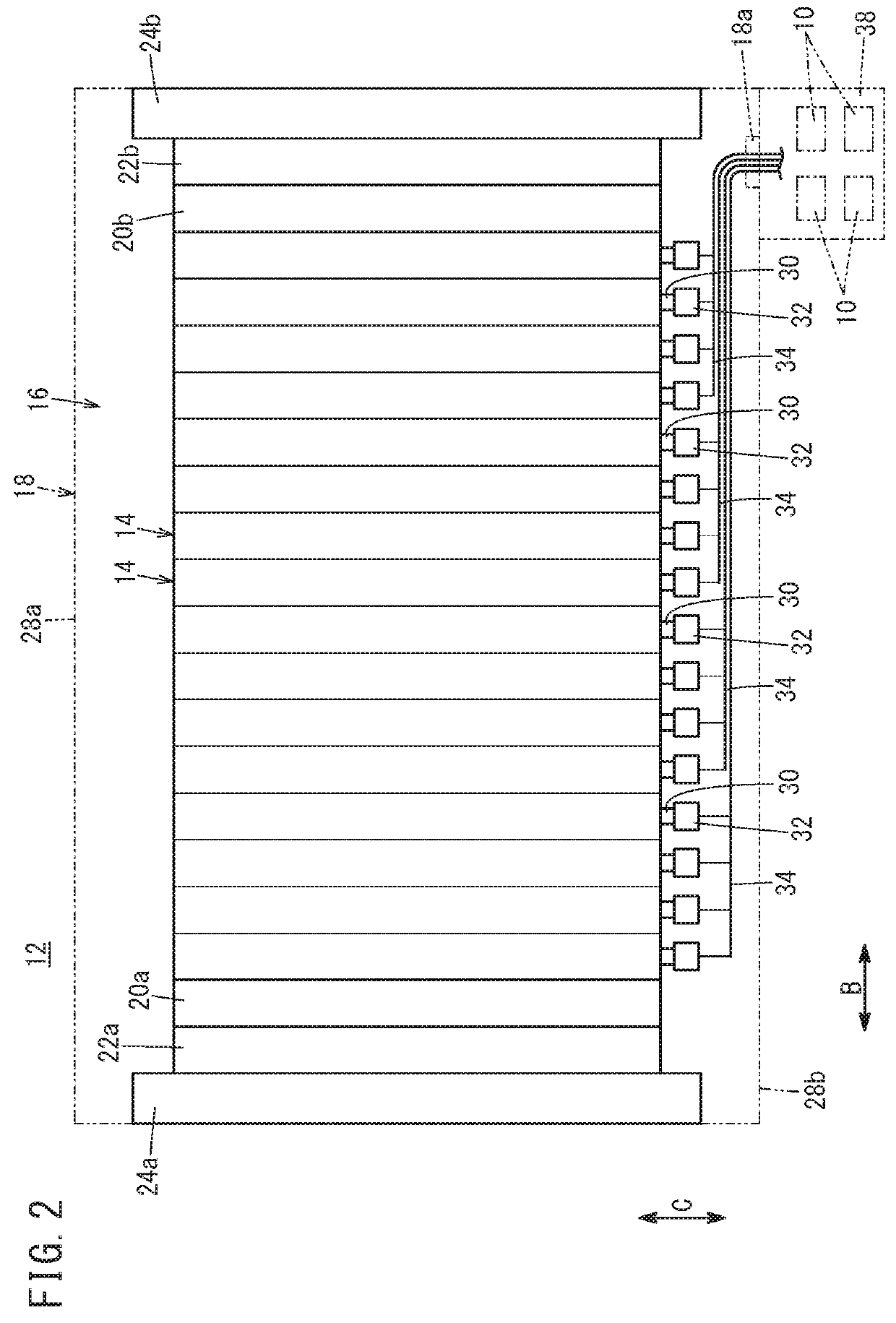
[0026]As shown in FIGS. 1 and 2, for example, a cable fixing structure 10 according to the embodiment of the present invention is used for a fuel cell stack 12 mounted in a fuel cell vehicle (not shown). The fuel cell stack 12 includes a cell stack body 16 formed by stacking a plurality of power generation cells (unit fuel cells) 14, and an accommodating case 18 accommodating the cell stack body 16.

[0027]In FIG. 2, at one end of the power generation cells 14 in a stacking direction, a first terminal plate 20a is provided. A first insulating plate 22a is provided outside the first terminal plate 20a, and a first end plate 24a is provided outside the first insulating plate 22a. At another end of the power generation cells 14 in the stacking direction, a second terminal plate 20b is prov...


PUM


Abstract

A cable fixing structure of a fuel cell stack fixes together a connector housing containing a substrate and a flat cable joined to the substrate. The cable fixing structure includes a fixing part provided for the connector housing, and having a convexly curved surface, and a heat contraction tube configured to surround the flat cable and the fixing part, and press the flat cable against the convexly curved surface.

Description

CROSS-REFERENCE TO RELATED APPLICATION[0001]This application is based upon and claims the benefit of priority from Japanese Patent Application No. 2016-205103 filed on Oct. 19, 2016, the contents of which are incorporated herein by reference.BACKGROUND OF THE INVENTIONField of the Invention[0002]The present invention relates to a cable fixing structure for fixing together a connector housing containing a substrate and a flat cable joined to the connector housing.Description of the Related Art[0003]As the cable fixing structure of this type, for example, Japanese Laid-Open Patent Publication No. 2009-266474 discloses a structure where a flat cable is sandwiched and held in a thickness direction of the flat cable, between two flat plate cable holders provided for a clamp part attached to a housing.SUMMARY OF THE INVENTION[0004]However, in the conventional technique like Japanese Laid-Open Patent Publication No. 2009-266474, since the flat cable is sandwiched and held in the thickness ...

Claims


Application Information

Patent Timeline
IPC IPC(8): H01M2/20H01M2/06H01R13/58H01R13/422H01M50/50
CPCH01M2/20H01M2/06H01R13/582H01R13/422H01M8/02H01R13/58H01M50/50H01R4/72H01R12/62H01R13/5808Y02E60/50Y02E60/10
Inventor SATO, MASAHIKOKOBAYASHI, TSUYOSHI
Owner HONDA MOTOR CO LTD
Why Eureka
Try Eureka