Driving tool

A technology of driving tools and drivers, applied in the direction of nailing tools, manufacturing tools, nailing staple tools, etc., to achieve the effect of inhibiting wear

Pending Publication Date: 2022-08-05
MAKITA CORP
View PDF1 Cites 0 Cited by
  • Summary
  • Abstract
  • Description
  • Claims
  • Application Information

AI Technical Summary

Problems solved by technology

In addition, it is necessary to provide a space for assembling the lubricating oil impregnated body to the lifter

Method used


Image

  • Driving tool
  • Driving tool
  • Driving tool

Examples


Embodiment Construction

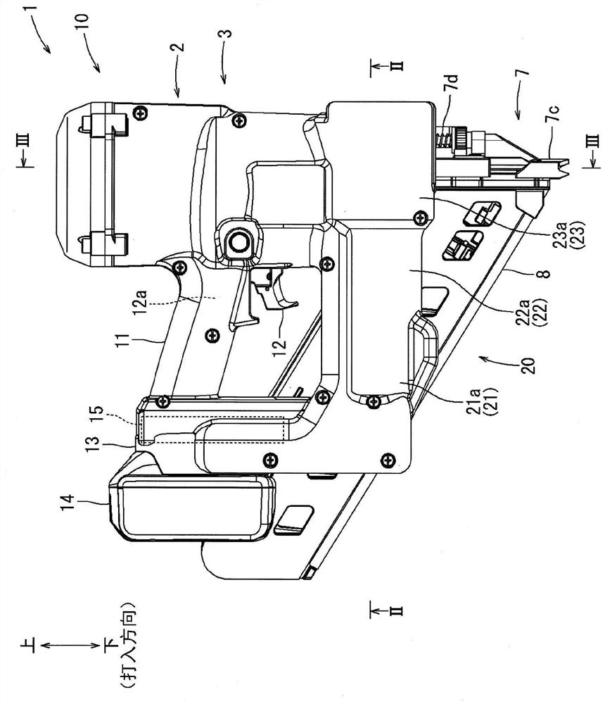
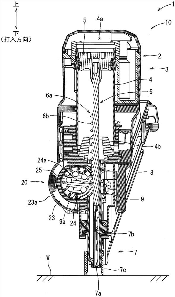
[0040] according to Figures 1 to 14 The driving tool 1 according to the first embodiment of the present invention will be described. In this embodiment, as a driving tool 1, a gas spring type driving tool is exemplified, which uses the air pressure of the gas (elastomer, fluid) enclosed in the pressure accumulating chamber 4a as a thrust for driving the driver n. like figure 1 As shown, the driving tool 1 has a tool body 10 having a substantially cylindrical body casing 2 and a handle portion 11 ; the handle portion 11 extends from the side of the tool body 10 . The top end of the tool body 10 is provided with a driving protrusion 7, and the driving protrusion 7 abuts against the material W to be driven to inject the driving piece n (see Figure 4 ). In the following description, the up-down direction is defined with the driving direction being down.

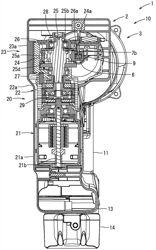
[0041] like image 3 As shown, the tool main body 10 has a driving mechanism 3 for driving the driving tool n downward. T...


PUM


Abstract

The invention provides a driving tool. There has been a need to supply highly viscous lubricating oil to the surface of an engagement pin of a lifter and suppress wear of the engagement pin. The driving tool is provided with a driver which impacts the driving member and an elastic body which applies downward force to the driver. The driving tool has a lifter that can be rotated by an electric motor as a power source and moves a driver to an upper dead center against the biasing force of an elastic body. The actuator has a plurality of meshing teeth arranged in a straight line. The lifter has a plurality of engagement pins disposed in the circumferential direction so as to be capable of engaging with the plurality of meshing teeth, and a wheel portion provided in the circumferential direction with a plurality of pin support holes that hold both ends of the plurality of engagement pins. The lifter is provided with: a grease groove which is adjacent to a pin support hole that supports the final pin and which penetrates the wheel section in the direction in which the pin support hole extends; the grease reservoir is recessed so as to be adjacent to the grease groove.

Description

technical field [0001] The present invention relates to a driving tool for driving nails, staples, etc., into wood and the like. Background technique [0002] A driving tool is known which strikes a driving piece by driving a driver by means of an elastic body such as a gas spring, a mechanical spring or the like. The gas spring-type driving tool disclosed in Patent Document 1 includes a driver for striking a driver, a driving mechanism for driving the driver downward, and a lifter for moving the driver upward. The driving mechanism has a piston and a cylinder that form a pressure accumulating chamber. The elastomer (gas) sealed in the pressure accumulating chamber stores the driving energy for driving the driver. The driver is provided integrally with the piston. The lifter has an engagement pin that can be engaged with the meshing teeth of the rack provided in the driver. [0003] In the first stage of the driving operation, the lifter holds the driver at the standby p...

Claims


Application Information

Patent Timeline
Patent Type & Authority Applications(China)
IPC IPC(8): B25C1/06B25C5/15B25F5/00
CPCB25C1/06B25C5/15B25F5/00B25C1/047B23Q11/1092
Inventor 马场德和
Owner MAKITA CORP
Why Eureka
Try Eureka