Cable fixing structure

a technology of fixing structure and cable, applied in the direction of current conducting connection, cell components, coupling device connection, etc., can solve the problems of excessive stress applied to the joint portion of the solder part, undesired electrical connection between the flat cable and the substrate, etc., to reduce the stress applied and suppress the situation

Active Publication Date: 2019-06-11
HONDA MOTOR CO LTD
View PDF11 Cites 0 Cited by
  • Summary
  • Abstract
  • Description
  • Claims
  • Application Information

AI Technical Summary

Benefits of technology

[0005]The present invention has been made taking the above problems into account, and an object of the present invention is to provide a cable fixing structure in which, when a pulling force is applied to a flat cable in a longitudinal direction of the flat cable, it is possible to reduce the stress applied to a joint portion between a substrate and the flat cable, and suppress interruption of electrical connection between the flat cable and the substrate.
[0016]In the present invention, the flat cable is pressed by the heat contraction tube against the convexly curved surface. Therefore, when a pulling force in a longitudinal direction is applied to the flat cable, it is possible to reduce the stress applied to the joint portion between the flat cable and the substrate, and suppress the situation where electrical connection between the flat cable and the substrate is interrupted.

Problems solved by technology

However, in the conventional technique like Japanese Laid-Open Patent Publication No. 2009-266474, since the flat cable is sandwiched and held in the thickness direction, between the flat plate cable holders, when a pulling force is applied to the flat cable in a longitudinal direction of the flat cable (pulling force in a direction to pull the flat cable from the connector housing), an excessive stress is applied to a solder part (joint portion), and electrical connection between the flat cable and the substrate may be interrupted undesirably.

Method used


Image

  • Cable fixing structure
  • Cable fixing structure
  • Cable fixing structure

Examples


Embodiment Construction

[0025]Hereinafter, a preferred embodiment of a cable fixing structure according to the present invention will be described in relation to a fuel cell system, with reference to the accompanying drawings.

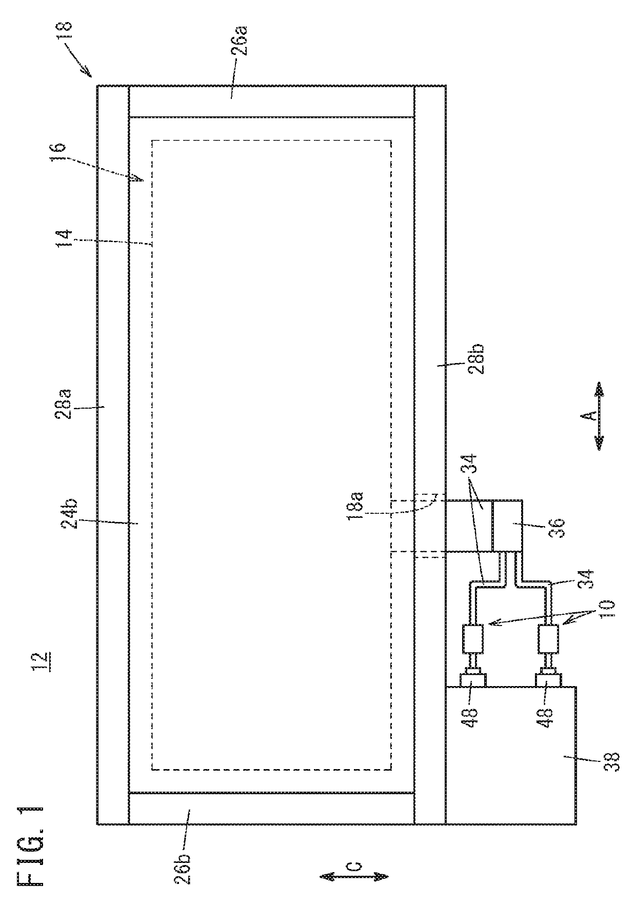
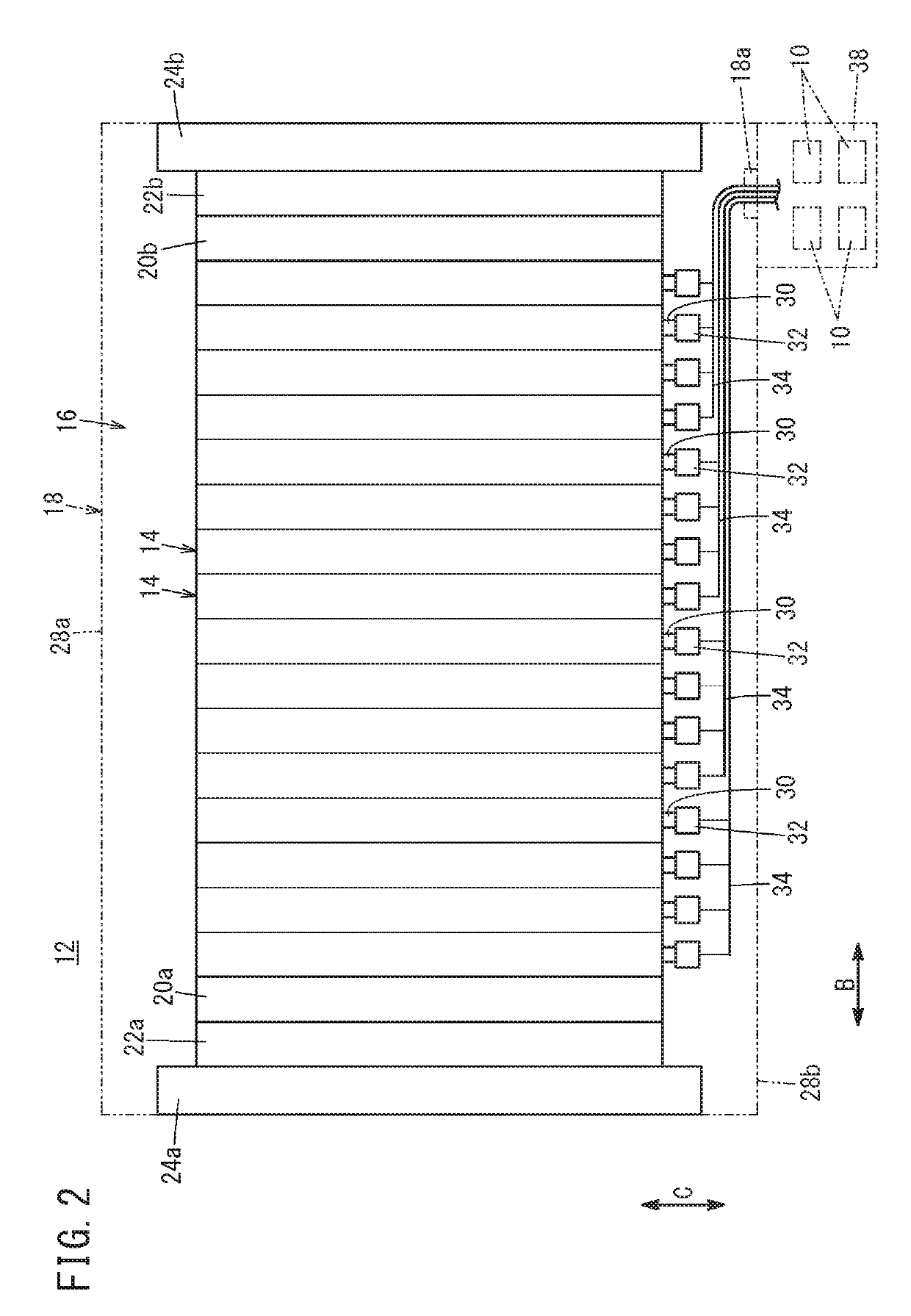
[0026]As shown in FIGS. 1 and 2, for example, a cable fixing structure 10 according to the embodiment of the present invention is used for a fuel cell stack 12 mounted in a fuel cell vehicle (not shown). The fuel cell stack 12 includes a cell stack body 16 formed by stacking a plurality of power generation cells (unit fuel cells) 14, and an accommodating case 18 accommodating the cell stack body 16.

[0027]In FIG. 2, at one end of the power generation cells 14 in a stacking direction, a first terminal plate 20a is provided. A first insulating plate 22a is provided outside the first terminal plate 20a, and a first end plate 24a is provided outside the first insulating plate 22a. At another end of the power generation cells 14 in the stacking direction, a second terminal plate 20b is prov...


PUM

PropertyMeasurementUnit
compression ratioaaaaaaaaaa
voltageaaaaaaaaaa
widthaaaaaaaaaa

Abstract

A cable fixing structure of a fuel cell stack fixes together a connector housing containing a substrate and a flat cable joined to the substrate. The cable fixing structure includes a fixing part provided for the connector housing, and having a convexly curved surface, and a heat contraction tube configured to surround the flat cable and the fixing part, and press the flat cable against the convexly curved surface.

Description

CROSS-REFERENCE TO RELATED APPLICATION[0001]This application is based upon and claims the benefit of priority from Japanese Patent Application No. 2016-205103 filed on Oct. 19, 2016, the contents of which are incorporated herein by reference.BACKGROUND OF THE INVENTIONField of the Invention[0002]The present invention relates to a cable fixing structure for fixing together a connector housing containing a substrate and a flat cable joined to the connector housing.Description of the Related Art[0003]As the cable fixing structure of this type, for example, Japanese Laid-Open Patent Publication No. 2009-266474 discloses a structure where a flat cable is sandwiched and held in a thickness direction of the flat cable, between two flat plate cable holders provided for a clamp part attached to a housing.SUMMARY OF THE INVENTION[0004]However, in the conventional technique like Japanese Laid-Open Patent Publication No. 2009-266474, since the flat cable is sandwiched and held in the thickness ...

Claims


Application Information

Patent Timeline
Patent Type & Authority Patents(United States)
IPC IPC(8): H01R4/72H01R13/58H01M2/06H01M2/20H01R13/422H01M8/02H01R12/62H01M50/50
CPCH01M2/20H01M2/06H01R13/422H01R13/5808H01R13/582H01R12/62H01M8/02H01R4/72H01R13/58H01M50/50Y02E60/50Y02E60/10
Inventor SATO, MASAHIKOKOBAYASHI, TSUYOSHI
Owner HONDA MOTOR CO LTD
Why Eureka
Try Eureka