Ultrasonic bonding tool and ultrasonic bonding method

a technology of ultrasonic bonding and ultrasonic bonding, which is applied in the direction of cell components, cell component details, manufacturing tools, etc., can solve the problems of ultrasonic bonding, which is more difficult to fuse the synthetic resin layers by heat, and the typical use of ultrasonic bonding to join such sheet-form separators, etc., to suppress the phenomenon of workpiece becoming affixed and suppress adhesion

Active Publication Date: 2020-04-21
ENVISION AESC JAPAN LTD
View PDF27 Cites 0 Cited by
  • Summary
  • Abstract
  • Description
  • Claims
  • Application Information

AI Technical Summary

Benefits of technology

[0008]Forming quadrangular pyramid shapes having apex angles greater than 90° in this manner suppresses adhesion between synthetic resin sheets constituting a workpiece and the side surfaces of the protrusions that bite into the synthetic resin sheets. Therefore, it is possible to suppress a phenomenon of the workpiece becoming affixed to the tool after ultrasonic bonding.

Problems solved by technology

Using an interposed heat-resistant layer composed of ceramic particles makes it more difficult to fuse the synthetic resin layers by heat.
Joining such sheet-form separators by ultrasonic bonding typically used to join current collectors of positive / negative electrodes and electrode tabs in the production of layered batteries is problematic, however, in that molten resin material readily adheres to knurled protrusions provided to a horn and / or an anvil.

Method used


Image

  • Ultrasonic bonding tool and ultrasonic bonding method
  • Ultrasonic bonding tool and ultrasonic bonding method
  • Ultrasonic bonding tool and ultrasonic bonding method

Examples


Embodiment Construction

[0017]A working example applied to an ultrasonic bonding tool for use in joining a bag-shaped separator of a layered battery cell is described below as a working example of this invention.

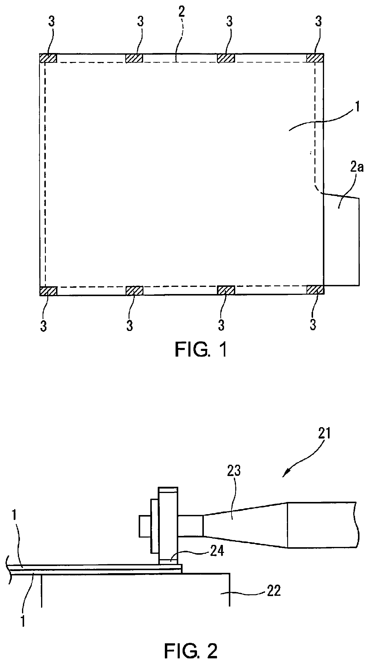
[0018]FIG. 1 shows a bagged electrode as a workpiece. The bagged electrode is configured as a so-called layered electrode assembly by joining together two sheet-form separators 1 at peripheral edges to form a bag-shaped body, sandwiching a positive electrode 2 in the bag-shaped body, and layering the bagged electrode in an alternating manner with a negative electrode (not shown), as disclosed in Patent Citation 1.

[0019]The sheet-form separators 1 are cut into a rectangular shape slightly larger than the positive electrode 2, and are joined together by ultrasonic bonding at joints 3 in a plurality of locations on peripheral edges, e.g., a total of eight locations such as are shown in FIG. 1. Part of a current collector of the positive electrode 2 extends from one side of the separators 1 as a tab 2a...


PUM

PropertyMeasurementUnit
apex angleaaaaaaaaaa
apex anglesaaaaaaaaaa

Abstract

An ultrasonic bonding tool is used on a horn side or anvil side of an ultrasonic joining device in which two synthetic resin sheets that include a polyethylene layer, a polypropylene layer and a ceramic heat-resistant layer are superposed and joined together so that the heat-resistant layers face each other. The ultrasonic bonding tool includes a plurality of protrusions shaped as quadrangular pyramids having a flat top surface. Each of the protrusions has an apex angle formed by two mutually opposite side surfaces that is within a range of 110-130°. When two separators of a battery cell are joined together using the ultrasonic bonding device with the ultrasonic bonding tool, a force with which the separators adhere to the protrusions is weak. In this way, the separators do not adhere to the horn during ultrasonic bonding of the synthetic resin sheets.

Description

CROSS-REFERENCE TO RELATED APPLICATIONS[0001]This application is a U.S. national stage application of International Application No. PCT / JP2016 / 088908, filed on Dec. 27, 2016.BACKGROUNDTechnological Field[0002]This invention relates to an improvement in an ultrasonic bonding tool provided with protrusions used on a horn side or anvil side of an ultrasonic bonding device in which synthetic resin sheets are superposed and joined together.Background Information[0003]International Publication No. 2014 / 058001 (Patent Citation 1) indicates that a sheet-form separator is placed between positive and negative electrodes in a layered battery such as a lithium ion secondary battery. In the separator, a heat-resistant layer composed of ceramic particles is provided on one surface of a synthetic resin layer made of polypropylene or the like. A so-called bagged electrode is then obtained by sandwiching an electrode, e.g., a positive electrode, between two separators, and joining peripheral edges o...

Claims


Application Information

Patent Timeline
Patent Type & Authority Patents(United States)
IPC IPC(8): B32B7/00B29C65/00B29C65/08H01M2/14B29K23/00B29L31/34H01M50/403H01M50/466
CPCB29C66/81433B29C66/72325B29C66/71B29C66/73921H01M2/145B29C66/341B29C65/081B29C66/21B29C66/433B29L2031/3468B29K2023/06B29C66/727B29K2023/12B29C66/73115B23K20/10B29C65/8223B29C66/1122B29C66/9516B29C66/9592Y02E60/10H01M50/403H01M50/466
Inventor NAKANO, TAKAHIRO
Owner ENVISION AESC JAPAN LTD
Why Eureka
Try Eureka