At-cut crystal element and crystal resonator

a technology of crystal elements and crystal resonators, which is applied in the direction of impedence networks, electrical devices, piezoelectric/electrostrictive/magnetostrictive devices, etc., can solve the problem of difficult crystal elements for crystal resonators to be manufactured by mechanical processing, and achieve the effect of reducing unnecessary vibration

Active Publication Date: 2020-04-28
NIHON DEMPA KOGYO CO LTD
View PDF16 Cites 0 Cited by
  • Summary
  • Abstract
  • Description
  • Claims
  • Application Information

AI Technical Summary

Benefits of technology

[0018]According to the AT-cut crystal element of the invention, the Z′-side surface constituted of predetermined three surfaces achieves the crystal element that has a unique beak shaped structure portion on the end portion in the Z′-direction of the crystal element in a sectional view. Therefore, the above-described unique structure portion reduces unnecessary vibration other than vibration originated from the AT-cut, thus the vibration originated from the AT-cut crystal resonator can be dominantly generated. Accordingly, the AT-cut crystal resonator whose property is improved compared with a conventional AT-cut crystal resonator can be achieved.

Problems solved by technology

As downsizing of an AT-cut crystal resonator proceeds, it has become difficult to fabricate crystal elements for crystal resonators by a fabrication method of mechanical processing.

Method used


Image

  • At-cut crystal element and crystal resonator
  • At-cut crystal element and crystal resonator
  • At-cut crystal element and crystal resonator

Examples


Embodiment Construction

[0030]The following describes the embodiments of an AT-cut crystal element and a crystal resonator that employs the AT-cut crystal element according to the present invention with reference to drawings. Each drawing used in descriptions are merely illustrated schematically for understanding the embodiments. In each drawing used in descriptions, like reference numerals designate corresponding or identical elements, and therefore such elements will not be further elaborated here. Shapes, dimensions, material, and similar factor described in the following explanations are merely preferable examples within the embodiments. Therefore, the disclosure is not limited to only the following embodiments.

[0031]1. Structure of AT-Cut Crystal Element

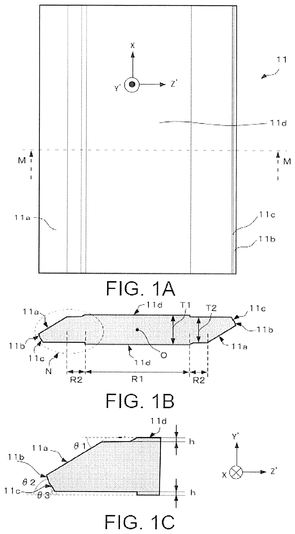
[0032]FIG. 1A to FIG. 1C are explanatory drawings illustrating an AT-cut crystal element 11 according to the embodiment. Especially, FIG. 1(A)FIG. 1A is a plan view of the crystal element 11, FIG. 1(B)FIG. 1B is a sectional drawing of the crystal eleme...


PUM

PropertyMeasurementUnit
oscillation frequencyaaaaaaaaaa
thickness T1aaaaaaaaaa

Abstract

An AT-cut crystal element is provided for reducing unnecessary vibration and for improving impedance of a resonator. Two side surfaces intersecting with a Z′-axis of a crystallographic axis of crystal are constituted of three surfaces of a first surface as an m-surface of quartz crystal, a second surface that intersects with the first surface and is other than the m-surface, and a third surface that intersects with the second surface and is other than the m-surface. Moreover, the second surface is a surface corresponding to a surface obtained by rotating a principal surface of the AT-cut crystal element by −74±3° having an X-axis of crystal as a rotation axis, and the third surface is a surface corresponding to a surface obtained by rotating the principal surface by −56±3° having the X-axis of the crystal as the rotation axis.

Description

CROSS-REFERENCE TO RELATED APPLICATION[0001]This application is a 371 application of the international PCT application serial no. PCT / JP2016 / 058474, filed on Mar. 17, 2016, which claims the priority benefits of Japan application no. 2015-082946, filed on Apr. 15, 2015. The entirety of each of the abovementioned patent applications is hereby incorporated by reference herein and made a part of this specification.TECHNICAL FIELD[0002]The present invention relates to an AT-cut crystal element and a crystal resonator using the same.BACKGROUND ART[0003]As downsizing of an AT-cut crystal resonator proceeds, it has become difficult to fabricate crystal elements for crystal resonators by a fabrication method of mechanical processing. Then, an AT-cut crystal element fabricated using photolithography technique and wet etching technique has been developed.[0004]A known AT-cut crystal element and crystal resonator fabricated by the above-described techniques is disclosed in, for example, Patent ...

Claims


Application Information

Patent Timeline
Patent Type & Authority Patents(United States)
IPC IPC(8): H03H9/13H03H9/02H01L41/332H03H3/02H03H9/10H03H9/19H03H3/04
CPCH03H9/132H03H9/02023H03H9/19H03H3/02H03H9/1021H03H9/10H01L41/332H03H2003/022H03H2003/0435H10N30/082
Inventor YAMAUCHI, HIROYUKIOSAWA, KAZUHIKOTAKEDA, SHOHEI
Owner NIHON DEMPA KOGYO CO LTD
Why Eureka
Try Eureka