Piezoelectric device

a technology of piezoelectric devices and crystal impedance, which is applied in the direction of piezoelectric/electrostrictive/magnetostrictive devices, electrical equipment, generator stabilization, etc., can solve the problems of possible deformation of crystal impedance (ci) and difficulty in solving this problem also by simulation

Active Publication Date: 2020-06-02
NIHON DEMPA KOGYO CO LTD
View PDF9 Cites 0 Cited by
  • Summary
  • Abstract
  • Description
  • Claims
  • Application Information

AI Technical Summary

Benefits of technology

[0057]With the piezoelectric device according to the embodiment, unnecessary vibration can be reduced without degrading a temperature characteristic.

Problems solved by technology

However, when the adhesive is applied on the piezoelectric substrate as shown in Japanese Unexamined Patent Application Publication No. 2003-309446, compared with a piezoelectric device on which such adhesive is not applied, temperature characteristic such as crystal impedance (CI) is possibly degraded.
In ensuring high accuracy of the piezoelectric device, especially, slight undulation of the frequency whose frequency change rate is 0.2 ppm or less in the unnecessary vibration causes a problem.
Since this slight undulation of the frequency is a complex system of a plurality of modes of vibration, it is difficult to solve this problem also by simulation.

Method used


Image

  • Piezoelectric device
  • Piezoelectric device
  • Piezoelectric device

Examples


second embodiment

[0044]The applied position and the applied state of the adhesive 152 may be modestly changed from the case in the first embodiment. The following describes a modification when the adhesive is applied on various positions or in various states.

[0045][Configuration of Piezoelectric Device 200]

[0046]FIG. 6A is a plan view of a piezoelectric device 200 from which the lid 120 has been removed. The piezoelectric device 200 is includes the lid 120, the package 110, and the piezoelectric vibrating piece 140, and has an applied position of the adhesive 152 different from that of the piezoelectric device 100. At the piezoelectric device 200, the adhesive 152 applied on the top surface 140a of the piezoelectric vibrating piece 140 does not contact the conductive adhesive 151. The applied adhesive 152 is applied on only between the excitation electrode 141 and the conductive adhesive 151a, and is not applied on between the excitation electrode 141 and the conductive adhesive 151b. A distance bet...


PUM

PropertyMeasurementUnit
distanceaaaaaaaaaa
distanceaaaaaaaaaa
distanceaaaaaaaaaa

Abstract

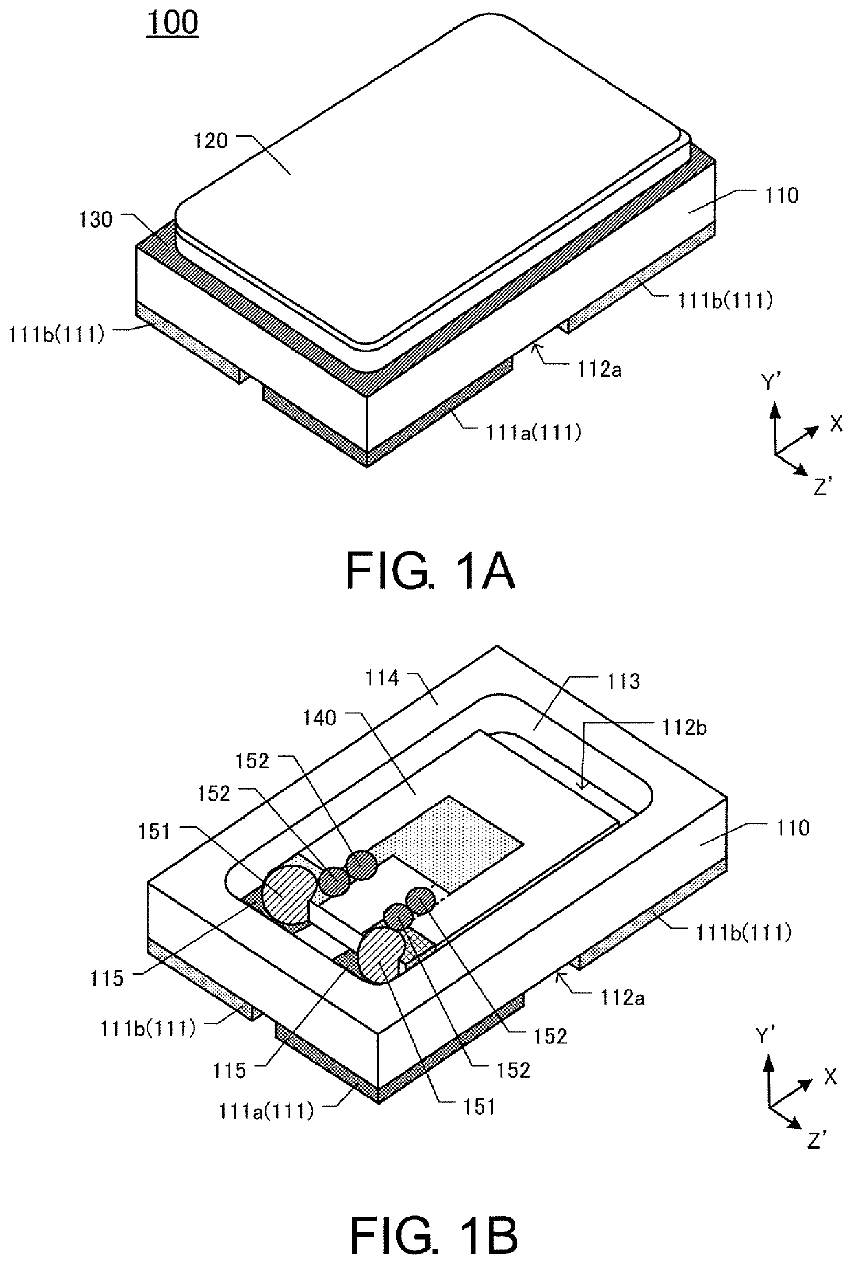
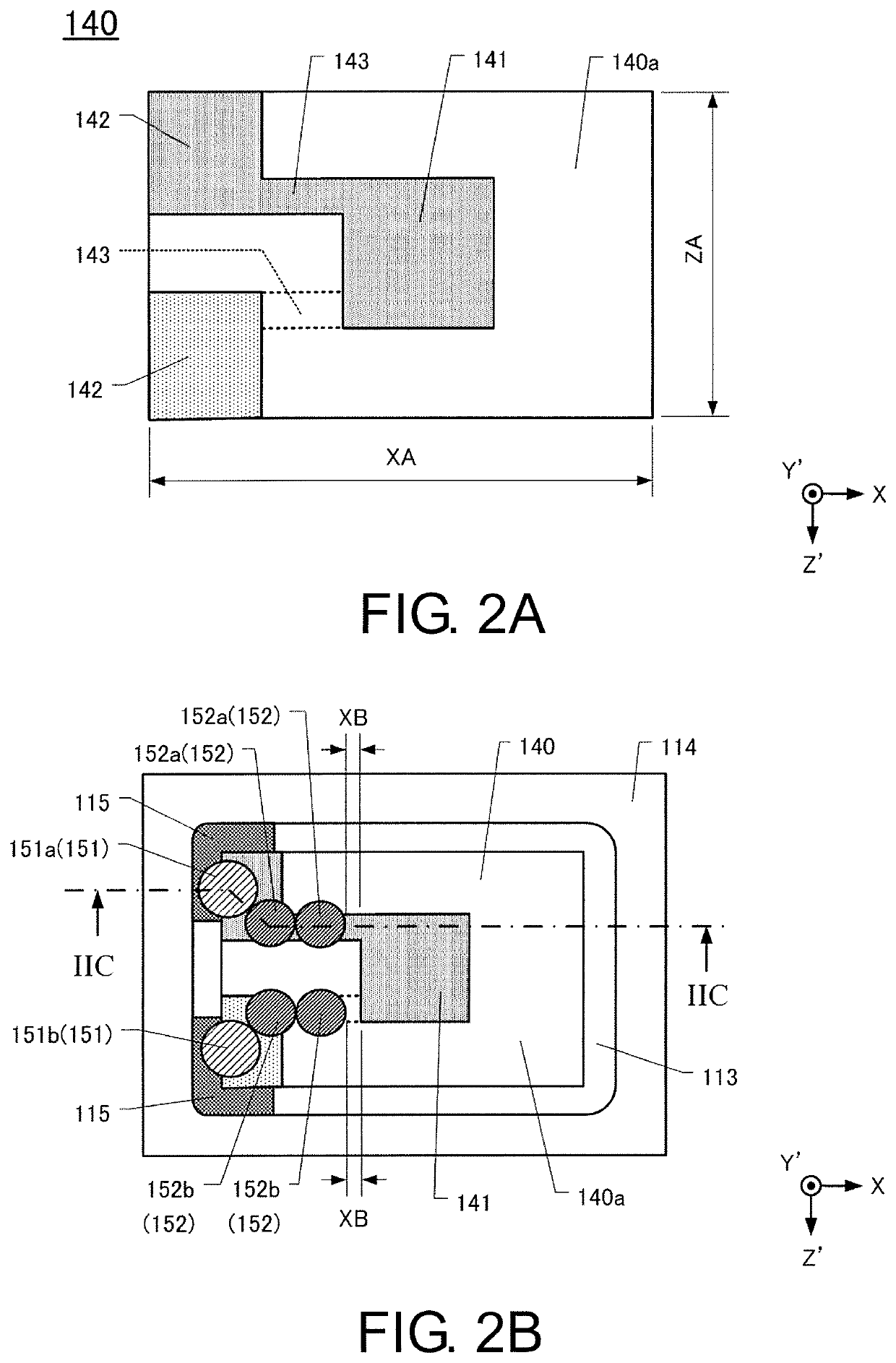
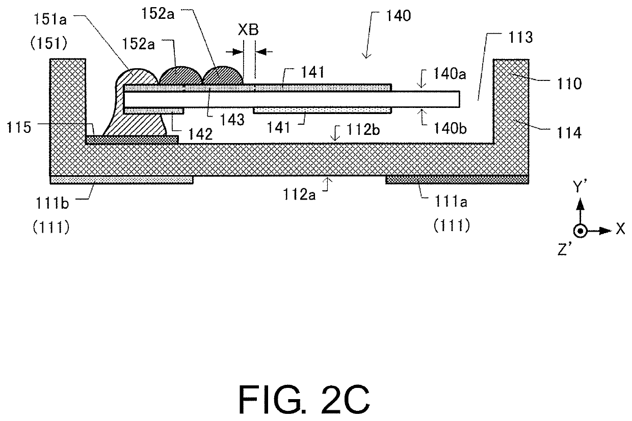
A piezoelectric device is provided and includes: a piezoelectric vibrating piece, having an outer shape in rectangular shape and including an excitation electrode formed on both principal surfaces which are a top surface and a lower surface, an electrode pad formed at both ends of one short side, and an extraction electrode extracted from the excitation electrode to the electrode pad to be electrically connected to the electrode pad; a package, including a placement surface on which the piezoelectric vibrating piece is placed as opposed to the lower surface of the piezoelectric vibrating piece, and an adhesion pad formed on the placement surface; and a conductive adhesive, securing the piezoelectric vibrating piece to the package and electrically connecting the adhesion pad to the electrode pad. An adhesive is applied on the top surface of the piezoelectric vibrating piece and between the conductive adhesive and the excitation electrode.

Description

CROSS-REFERENCE TO RELATED APPLICATIONS[0001]This application is based on and claims priority under 35 U.S.C. § 119 to Japanese Patent Application No. 2016-211609, filed on Oct. 28, 2016 the entire content of which is incorporated herein by reference.TECHNICAL FIELD[0002]This disclosure relates to a piezoelectric device having a piezoelectric vibrating piece on which an adhesive is applied.DESCRIPTION OF THE RELATED ART[0003]When a piezoelectric vibrating piece having a piezoelectric substrate on which an excitation electrode is formed is vibrated at a predetermined frequency, unnecessary vibration having a frequency different from that of main vibration is generated together with the main vibration. To prevent the generation of such unnecessary vibration, for example, Japanese Unexamined Patent Application Publication No. 2003-309446 shows that an adhesive is applied on a region where the excitation electrode is not formed on a principal surface of the piezoelectric substrate to pe...

Claims


Application Information

Patent Timeline
Patent Type & Authority Patents(United States)
IPC IPC(8): H03H9/19H01L41/053H03H9/05H01L41/047H03H3/02H03H9/10H03H9/21
CPCH03H9/0519H03H9/1021H01L41/053H03H9/19H01L41/0477H03H9/21H03H9/0509H03H3/02H03H2003/022H03H9/10H03H9/125H03H9/17H03L1/02H10N30/88H10N30/877
Inventor WATANABE, YOSHIHIRO
Owner NIHON DEMPA KOGYO CO LTD
Why Eureka
Try Eureka