Vibration wave motor and electronic equipment using vibration wave motor

a technology of vibration wave motor and vibration wave, which is applied in the direction of mechanical vibration separation, piezoelectric/electrostrictive/magnetostrictive devices, piezoelectric/electrostrictive/magnetostriction machines, etc., can solve the problems of noise generation, and affecting the operation of the motor. , to achieve the effect of reducing the thickness of the friction member and reducing the size and cos

Active Publication Date: 2021-11-30
CANON KK
View PDF8 Cites 0 Cited by
  • Summary
  • Abstract
  • Description
  • Claims
  • Application Information

AI Technical Summary

Benefits of technology

[0004]An object of the present invention is to provide a vibration wave motor including a damping member provided for the purpose of reducing unnecessary vibration of a friction member, thereby suppressing noise of the vibration wave motor caused by the unnecessary vibration of the friction member and achieving reduction in size and cost.
[0006]According to the one embodiment of the present invention, there can be provided a vibration wave motor including the damping member provided for the purpose of reducing unnecessary vibration of the friction member, thereby suppressing noise of the vibration wave motor caused by the unnecessary vibration generated in the friction member and achieving reduction in size and cost.

Problems solved by technology

However, when the friction member is reduced in thickness, intervals of resonance frequencies become smaller, with the result that resonance is liable to occur around a drive frequency band.
There has been a problem in that the resonance causes generation of unnecessary vibration of the friction member to cause degradation in characteristic of the ultrasonic motor and generation of noise.

Method used


Image

  • Vibration wave motor and electronic equipment using vibration wave motor
  • Vibration wave motor and electronic equipment using vibration wave motor
  • Vibration wave motor and electronic equipment using vibration wave motor

Examples


first embodiment

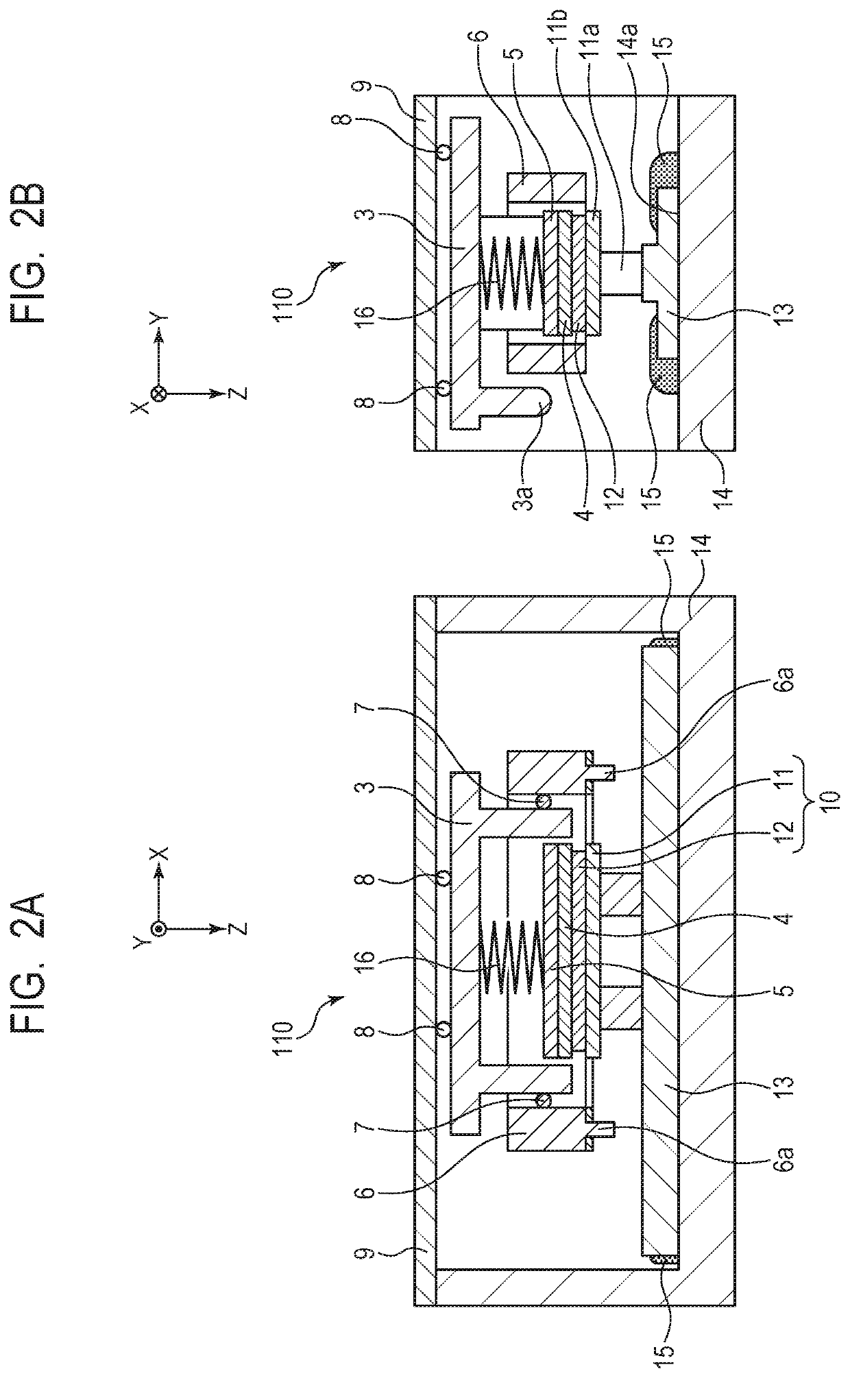
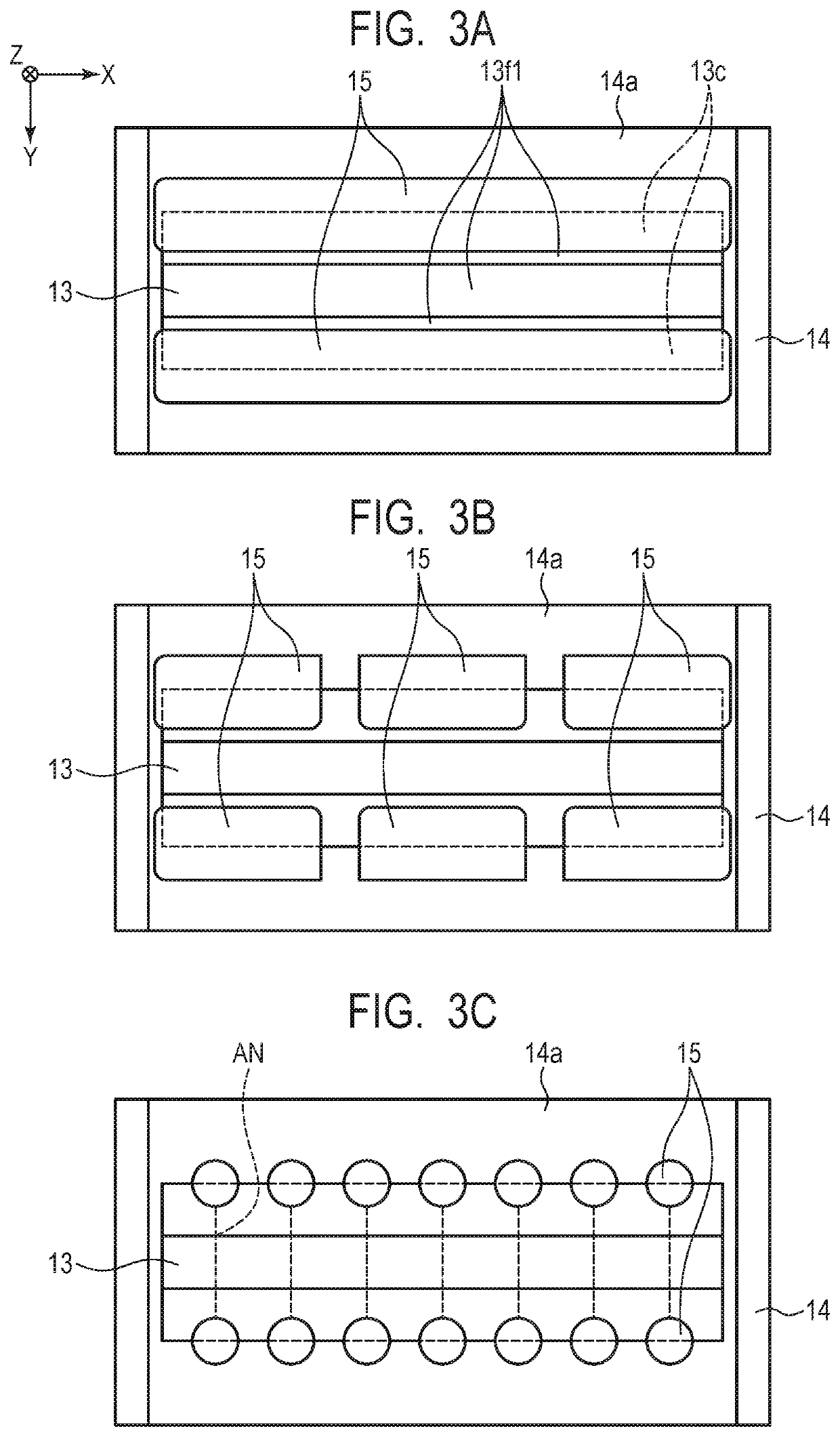
[0037]Description is made of a first embodiment of the present invention with reference to FIG. 2B, FIG. 4A, and FIG. 4B. The friction member 13 used for the vibration wave motor 110 according to the first embodiment includes the sliding side surfaces 13f1 and the fixing side surface 13f2, and the fixing side surface 13f2 is formed on a back side of the sliding side surfaces 13f1. On the sliding side surface 13f1 side, there are formed the sliding region 13a held in abutment against the projection portions 11a of the vibration body 10 and the damping regions 13c held in contact with the damping members 15. Meanwhile, on the fixing side surface 13f2, there is formed the fixing region 13b, which is held in abutment against a fixing surface 14a of the base member 14 to fix the friction member 13. The damping regions 13c extend in the relative movement direction, and are divided on both outer sides of the sliding region 13a and formed adjacent to the sliding region 13a in the orthogonal...

second embodiment

[0044]Next, description is made of a second embodiment of the present invention with reference to FIG. 5, FIG. 6A, and FIG. 6B. In the first embodiment, the entirety of the fixing side surface 13f2 of the friction member 13 corresponds to the fixing region 13b, and is held in contact with the fixing surface 14a of the base member 14. The damping regions 13c with which the damping members 15 are held in contact are formed only on the sliding side surface 13f1 side. In the second embodiment, damping regions 23c of a friction member 23 reduced in thickness are formed not only on sliding side surfaces 23f1 but also on a fixing side surface 23f2, and recessed portions 24b are formed in a base member 24. Those configurations are different from those of the first embodiment. Now, detailed description is made of configurations different from those of the first embodiment.

[0045]FIG. 5 is a sectional view for illustrating a configuration of a vibration wave motor 120 according to the second e...

third embodiment

[0051]Next, description is made of a third embodiment of the present invention with reference to FIG. 7 to FIG. 9A and FIG. 9B. In the second embodiment, the friction member 23 has the T-shaped cross section, and the sliding region 23a projects toward the vibration body 20 side with respect to the damping regions 23c so as to prevent the damping members 25 from spreading to the sliding region 23a. In the third embodiment, a friction member 33 having a thin plate shape with an even thickness is bent so that a sliding region 33a projects toward a vibration body 30 side with respect to damping regions 33c. That is, the third embodiment is different from the second embodiment in that the friction member 33 does not have a T-shaped cross section. Now, detailed description is made of configurations different from those of the second embodiment.

[0052]FIG. 7 is a sectional view for illustrating a configuration of a vibration wave motor 130 according to the third embodiment, and is an illust...


PUM


Abstract

Provided is a vibration wave motor, including: a vibration body; a friction member; a press member configured to pressurize the vibration body against the friction member; a base member configured to fix the friction member; and a damping member configured to damp vibration, wherein the vibration body and the friction member are configured to move relative to each other, wherein the friction member includes: a first surface having a first region held in abutment against the vibration body; and a second surface, which is a back surface of the first surface, and has a second region held in abutment against the base member, wherein at least one of the first surface and the second surface has a third region held in contact with the damping member, and wherein positions of the first region and the third region in a pressurizing direction of the press member are different from each other.

Description

BACKGROUND OF THE INVENTIONField of the Invention[0001]The present invention relates to a vibration wave motor, and more particularly, to a linear vibration wave motor including an elastic body having a plate shape, and to an electronic equipment configured to drive a driven member using the linear vibration wave motor.Description of the Related Art[0002]Hitherto, an ultrasonic motor having features of small size and weight, high-speed drive, and low-noise drive has been employed in an actuator for, for example, a lens barrel of an image pickup apparatus. There exist ultrasonic motors of various modes. Among the ultrasonic motors, an ultrasonic motor for linear drive is disclosed in Japanese Patent Application Laid-Open No. 2016-82802. The ultrasonic motor disclosed in Japanese Patent Application Laid-Open No. 2016-82802 includes a vibrator, a friction member (slider), and a press spring. The vibrator includes a piezoelectric element and a vibration plate. The friction member is hel...

Claims


Application Information

Patent Timeline
Patent Type & Authority Patents(United States)
IPC IPC(8): H02N2/00H02N2/08B06B1/06H01L41/09H02N2/02H01L41/08
CPCH02N2/001B06B1/06B06B1/0644H01L41/0825H01L41/09H02N2/006H02N2/0065H02N2/026H02N2/08H10N30/20H10N30/1071
Inventor NINOMIYA, SHUNSUKENAKABAYASHI, MAI
Owner CANON KK
Why Eureka
Try Eureka