Vibration-type actuator, driving method for vibration-type actuator, and electronic apparatus equipped with vibration-type actuator

a technology of vibration-type actuators and actuators, which is applied in the direction of electrical apparatus, generators/motors, electric/electrostriction/magnetostriction machines, etc., can solve the problems of abnormal noise, abnormal noise, and large abnormal noise, and achieve the effect of reducing unnecessary vibration during driving

Active Publication Date: 2019-10-08
CANON KK
View PDF24 Cites 1 Cited by
  • Summary
  • Abstract
  • Description
  • Claims
  • Application Information

AI Technical Summary

Benefits of technology

[0009]The present invention provides a vibration-type actuator that is capable of reducing an unnecessary vibration during driving.
[0013]According to the present invention, the unnecessary vibration during driving of the vibration-type actuator is reduced. This reduces an abnormal noise and enables stable driving.

Problems solved by technology

However, the vibration-type actuator using the vibration body 102 may cause an abnormal noise called a “squeal” in a high frequency range at a low driving speed, when the frequency of alternating voltage is swept so as to approach a resonance frequency in a vibration mode used for driving from a frequency higher than the resonance frequency.
When the unnecessary vibration occurs, the frequency difference between the frequency of the unnecessary vibration and the driving frequency becomes audible, which causes the abnormal noise.
Then, when the frequency difference between the resonance frequency in the vibration mode used for driving and the driving frequency is approximately coincident with the frequency difference between the frequency of the unnecessary vibration occurred and the driving frequency, while the driving frequency is further swept toward the low frequency side, the abnormal noise becomes large and the driving also becomes unstable.

Method used


Image

  • Vibration-type actuator, driving method for vibration-type actuator, and electronic apparatus equipped with vibration-type actuator
  • Vibration-type actuator, driving method for vibration-type actuator, and electronic apparatus equipped with vibration-type actuator
  • Vibration-type actuator, driving method for vibration-type actuator, and electronic apparatus equipped with vibration-type actuator

Examples


first embodiment

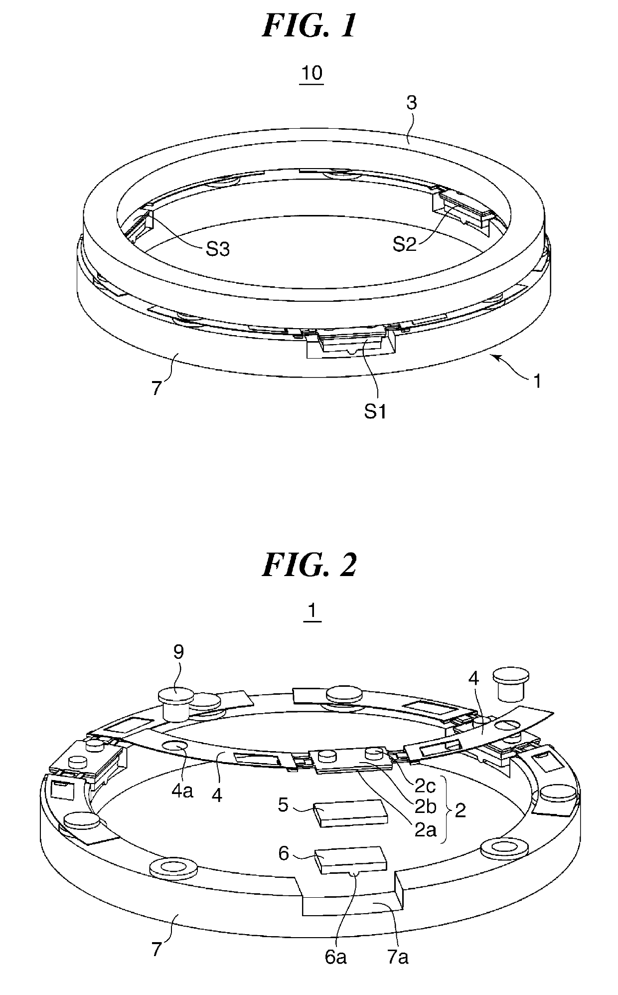
[0033]FIG. 1 is a perspective view schematically showing a configuration of a vibration-type actuator 10 according to the present invention. The vibration-type actuator 10 has a ring-shaped driving unit 1 and a ring-shaped driven body 3. A center axis of the driving unit 1 is approximately coincident with a center axis of the driven body 3. The driving unit 1 has three vibration body units S1, S2, and S3 that have the same configuration, and a ring-shaped base 7 that holds the vibration body units S1, S2, and S3. The vibration body units S1, S2, and S3 are arranged so as to divide the circumference of the base 7 into three equal parts approximately.

[0034]It should be noted that the number of the vibration body units that constitute the driving unit 1 is not limited to three and may be selected according to a required output characteristic. The number may be one, two, four, or more. When a vibration-type actuator is constituted using one or two vibration body units, it is preferable ...

second embodiment

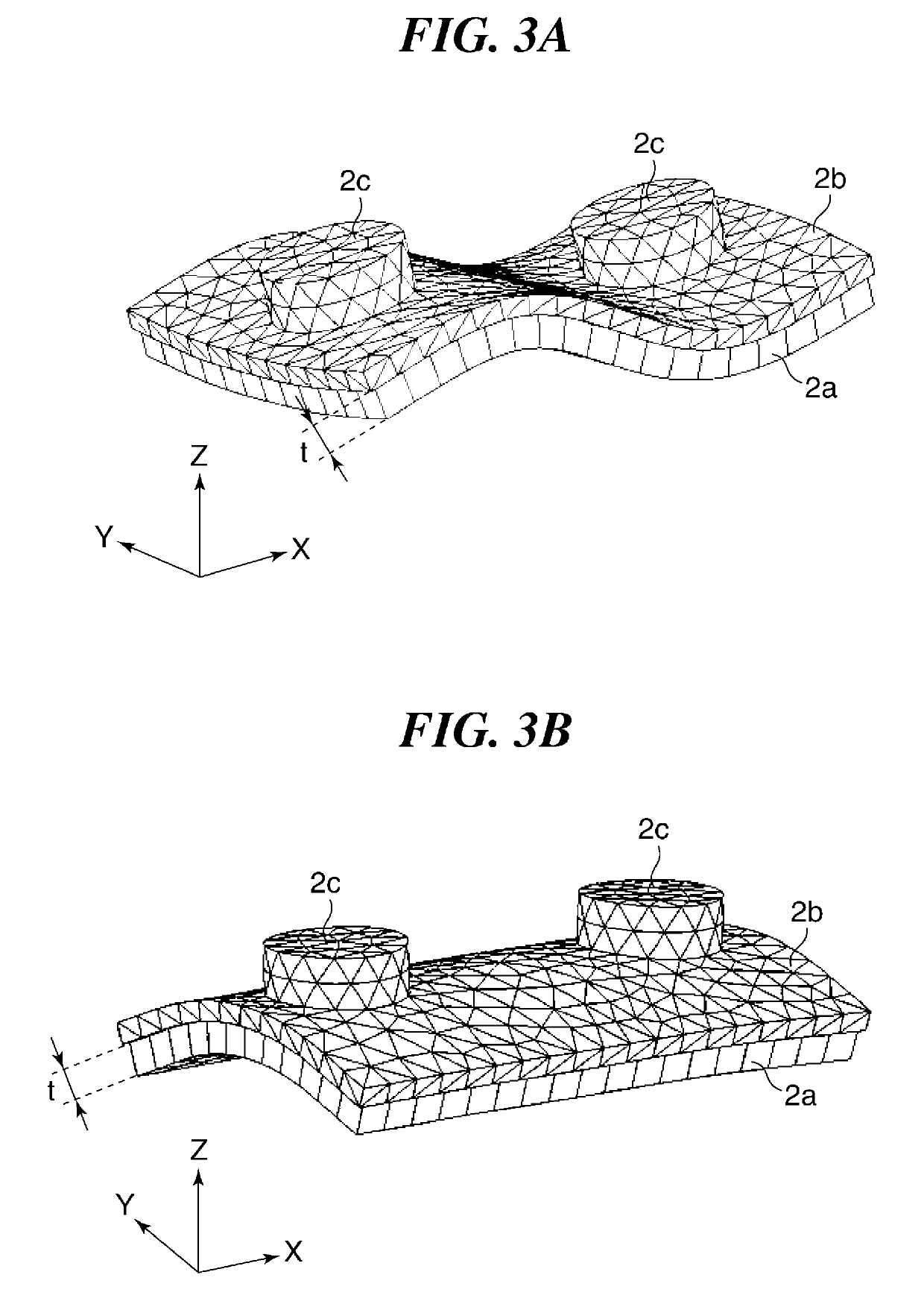
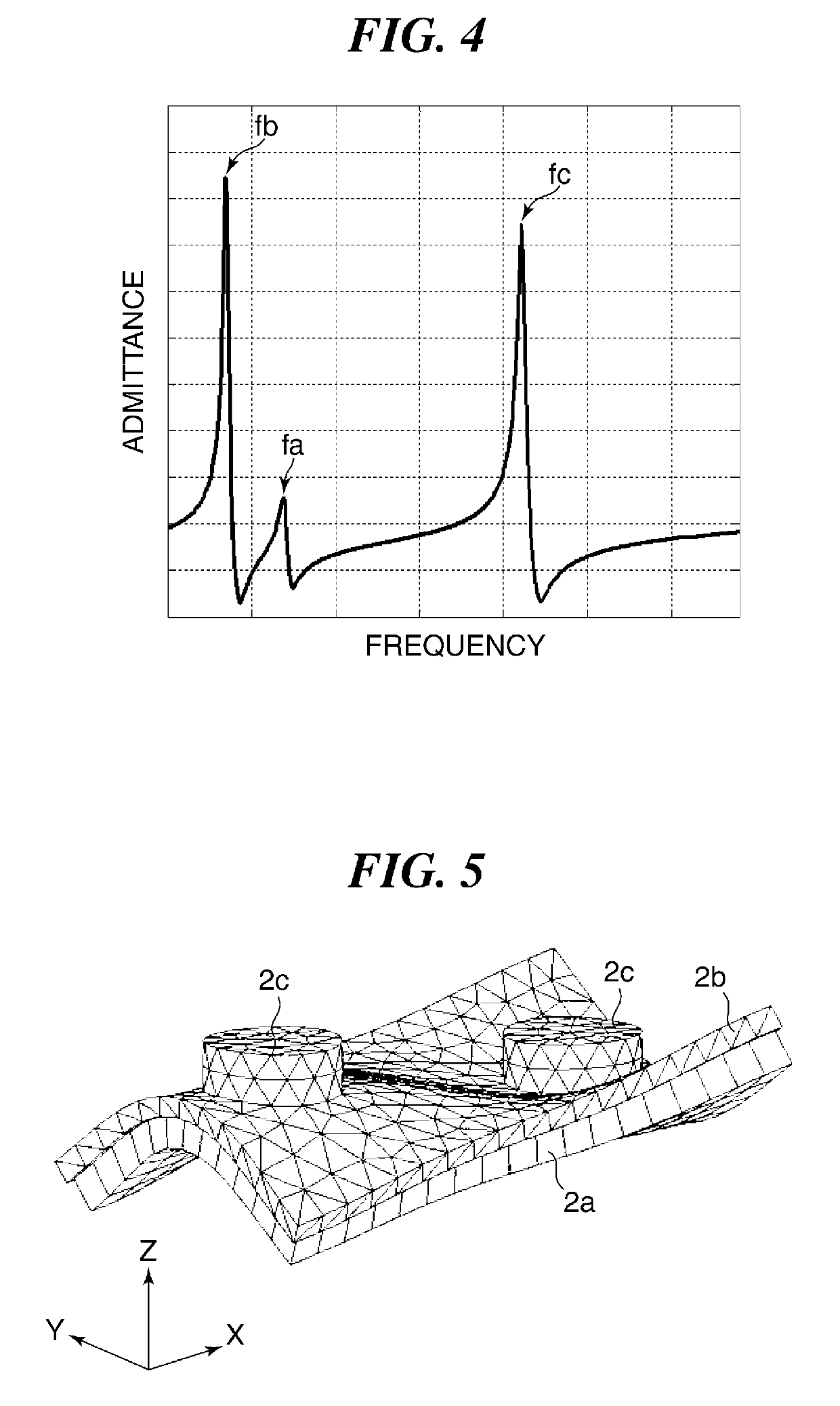
[0075]As mentioned above, the elastic body 22b constituting the vibration body 22 is shaped so that the frequency difference f3 is always larger than the frequency differences f1 and f2 in the driving frequency range of the vibration-type actuator in the Accordingly, the vibration in the third vibration mode that is an unnecessary vibration is reduced and generation of a squeal is reduced, which enables stable driving.

[0076]Although the corners of the elastic body 22b are removed (are cut out) along the straight lines in the second embodiment, it is not limited to this. The corners of the elastic body 22b may be cut out (may be formed) circularly. Moreover, the four corners of the piezoelectric device 22a may be removed similarly. And the four corners of the elastic body 22b and the four corners of the piezoelectric device 22a may be removed.

[0077]Next, a third embodiment of the present invention will be described. In the third embodiment, a configuration of an image pickup apparat...

third embodiment

[0084]Although the example that moves the lens groups in the optical axis direction using the ring-shaped vibration-type actuator 10 is described in the third embodiment, the configuration that moves the lens groups in the optical axis direction using the vibration body 2 is not limited to this. For example, the vibration body 2 is able to move the driven body in the X-direction that connects the two projections. Accordingly, a holding member holding a lens is used as the driven body, and one or more vibration bodies 2 are held on a base so that the optical axis direction of the lens, the driving direction of the driven body, and the X-direction of the vibration body 2 become parallel mutually.

[0085]Moreover, when the lens barrel includes an image stabilization lens, the vibration body unit S1 of which a shape and driving condition are designed so as to reduce unnecessary vibration may be employed in an image stabilization unit that moves the image stabilization lens in any directio...


PUM


Abstract

A vibration-type actuator that is capable of reducing an unnecessary vibration during driving includes a vibration body configured by connecting an electro-mechanical energy conversion element and an elastic body. A driven body is in pressure contact with the vibration body. A controller moves the vibration body and the driven body relatively by a vibration that is excited in the vibration body by applying driving voltage to the electro-mechanical energy conversion element so that a difference between a resonance frequency in a natural vibration mode of the vibration body that is higher than an upper limit frequency of a predetermined driving frequency range and that is nearest to the upper limit frequency and a frequency of the driving voltage is greater than a difference between a resonance frequency in a natural vibration mode used for moving the vibration body and the driven body relatively and the frequency of the driving voltage.

Description

BACKGROUND OF THE INVENTION[0001]Field of the Invention[0002]The present invention relates to a vibration-type actuator, a driving method for the vibration-type actuator, and an electronic apparatus equipped with the vibration-type actuator.[0003]Description of the Related Art[0004]There is a known vibration-type actuator that makes a vibration body be in pressure contact with a driven body and moves the vibration body and driven body relatively by a vibration excited in the vibration body (see Japanese Laid-Open Patent Publication (Kokai) No. 2004-320846 (JP 2004-320846A)).[0005]FIG. 15 is a perspective view schematically showing a configuration of a well-known vibration-type actuator 100. The vibration-type actuator 100 has a vibration body 102 and a driven body 103. The vibration body 102 has an elastic body 102b, two projections 102c disposed on one side of the elastic body 102b, and a piezoelectric device 102a joined to the elastic body 102b at the side opposite to the side on ...

Claims


Application Information

Patent Timeline
Patent Type & Authority Patents(United States)
IPC IPC(8): H02N2/10H02N2/00
CPCH02N2/0015H02N2/103H02N2/008
Inventor SUEFUJI, KEIKIMURA, ATSUSHIMORI, TAKAOTSUCHIYA, SATOSHISHIMADA, AKIRA
Owner CANON KK
Why Eureka
Try Eureka