Vibration wave motor and driving device including the vibration wave motor
a technology of vibration wave motor and driving device, which is applied in the direction of instruments, printers, cameras focusing arrangements, etc., can solve the problems of short connection distance between the vibrator and the member that exerts the driving force, abnormal noise, and vibration from the vibrator is liable to propagate, so as to reduce the occurrence of unnecessary vibration
- Summary
- Abstract
- Description
- Claims
- Application Information
AI Technical Summary
Benefits of technology
Problems solved by technology
Method used
Image

Examples
embodiment
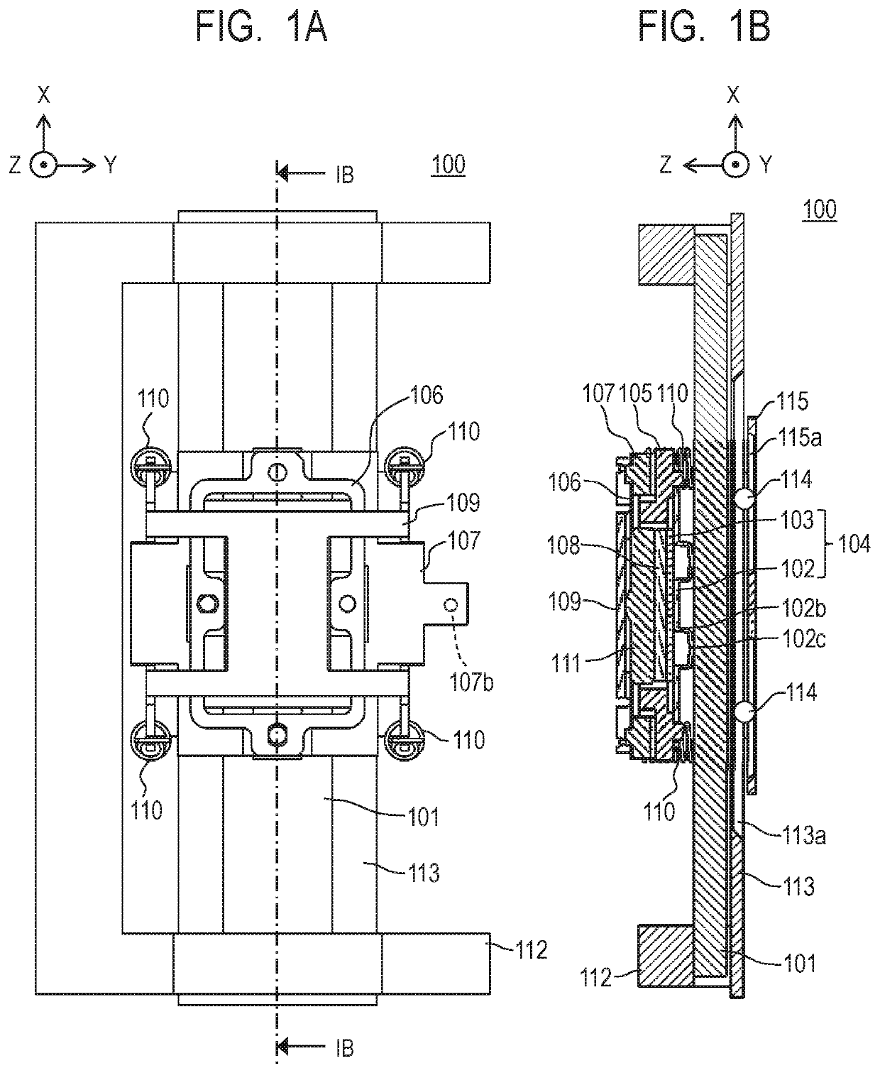
[0014]In the present specification, a direction, in which a vibrator 104 and a friction member 101 described later are configured to move relative to each other, is defined as an X-axis direction. Moreover, a pressurizing direction by springs 110 described later is defined as a Z-axis direction. Furthermore, a direction perpendicular to the X-axis direction and the Z-axis direction is defined as a Y-axis direction.
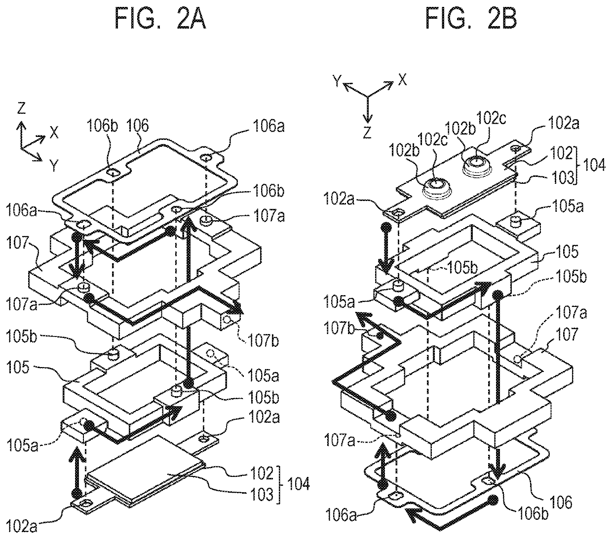
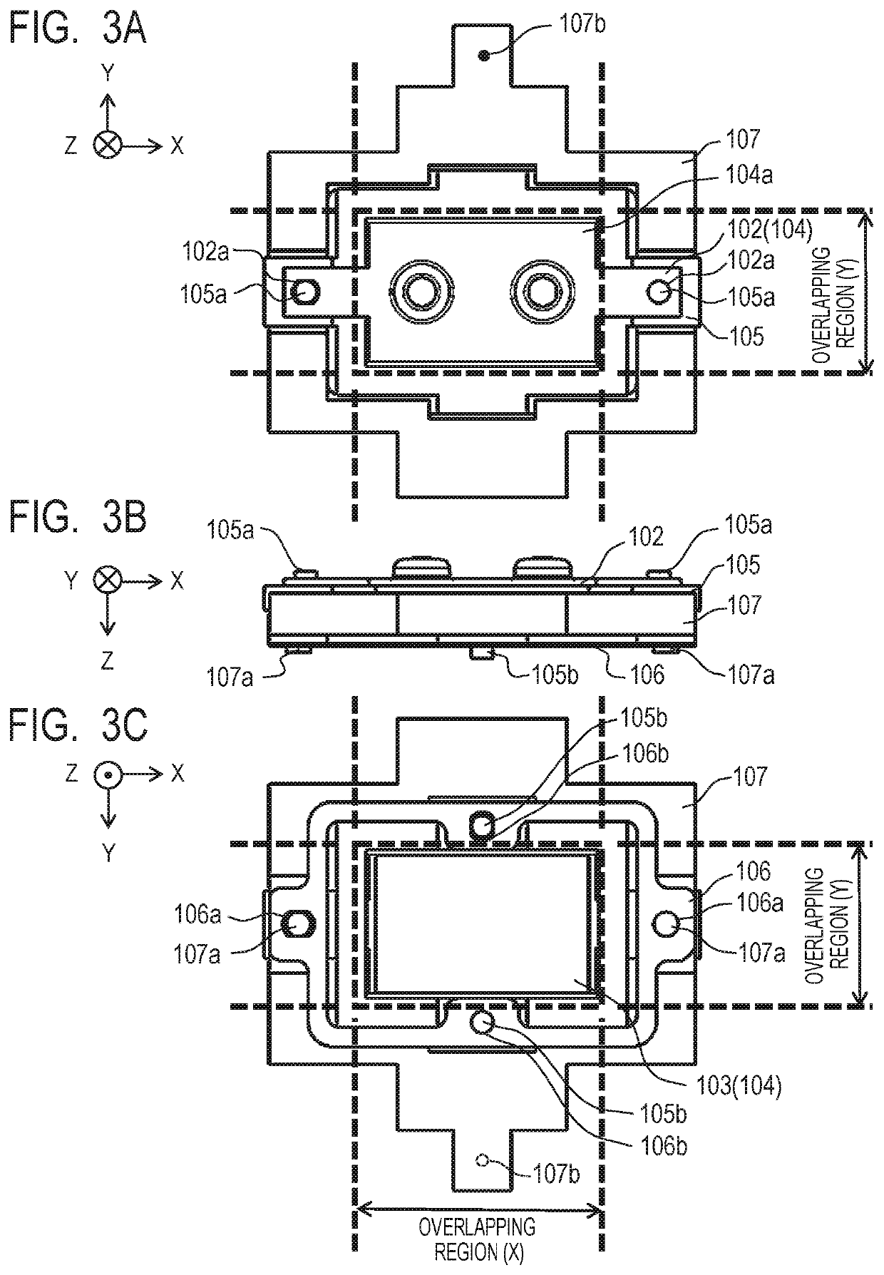
[0015]FIG. 1A is a plan view for illustrating a vibration wave motor 100 (ultrasonic motor) of an embodiment of the present disclosure when viewed in the Z-axis direction. FIG. 1B is a cross-sectional view for illustrating the vibration wave motor 100 taken along a cross-sectional line IB-IB illustrated in FIG. 1A. The vibration wave motor 100 in this embodiment includes a vibrator 104, a friction member 101, a first holding member 105, a second holding member 106, and a third holding member 107.
[0016]The vibrator 104 includes an elastic vibrating plate 102 and a piezoelec...
application example
[0034]FIG. 4 is a view for illustrating a configuration of an image pickup apparatus as an application example to which the vibration wave motor 100 of the present disclosure is applied. In this specification, a case will be described in which a lens barrel driving device equipped with the vibration wave motor 100 is mounted on the image pickup apparatus. However, this does not limit the present disclosure. Moreover, an image pickup apparatus, in which an image pickup lens unit 1 and a camera body 2 described later are integrated with each other, will be described. However, the image pickup lens unit 1 may be an exchangeable lens.
[0035]In FIG. 4, the image pickup lens unit 1 and the camera body 2 form an image pickup apparatus body. In the inside of the image pickup lens unit 1, the optical lens 3 is coupled to the connecting portion 107b of the third holding member 107 of the vibration wave motor 100, and the vibrator 104 that forms the vibration wave motor 100 moves, and hence the...
PUM
 Abstract
Description
Claims
Application Information