Face-sealing fluidic connection system

a fluid connection and assembly technology, applied in the direction of separation processes, instruments, glassware laboratories, etc., can solve the problems of wasting time and inefficiency, affecting the performance of the system, and affecting the reliability of the system, so as to achieve the effect of reducing the torque, quick and easy connection and disconnection

Active Publication Date: 2020-05-19
IDEX HEALTH & SCI
View PDF48 Cites 3 Cited by
  • Summary
  • Abstract
  • Description
  • Claims
  • Application Information

AI Technical Summary

Benefits of technology

[0026]It is therefore an object of the present disclosure to provide a fluidic connection system useful for high-pressure applications. The system can provide a sealing connection without the use of additional parts such as ferrules, locking rings, or other fittings. It is a further object of the present disclosure to provide a fluidic connection system, wherein the axial force necessary to create an effective seal for high-pressure applications can be generated manually, with minimal torque and without the use of tools. It is a further object of the present disclosure to provide a fluidic connection system which is flexible and can be quickly and easily connected and disconnected with various tubes and ports without damaging the connection system.
[0030]In another embodiment, a fitting assembly is provided in which a nut has one or more slots, which can extend the longitudinal length of the nut and which can extend radially from the passageway through the nut to the exterior of the nut. The nut can have one or more such slots, and the slots can extend along only a portion of the longitudinal length of the nut if desired. In addition, the slot can be adapted so that tubing can be easily inserted into the interior passageway of the nut by an operator, or can be easily removed from the nut by an operator. The slot is adapted so that a tube or a portion of a tube can be easily inserted into or removed from the nut through the slot.

Problems solved by technology

If the connection is too weak, it may leak.
Because the types of solvents that are sometimes used as the mobile phase are often toxic and because it is often expensive to obtain and / or prepare many samples for use, any such connection failure is a serious concern.
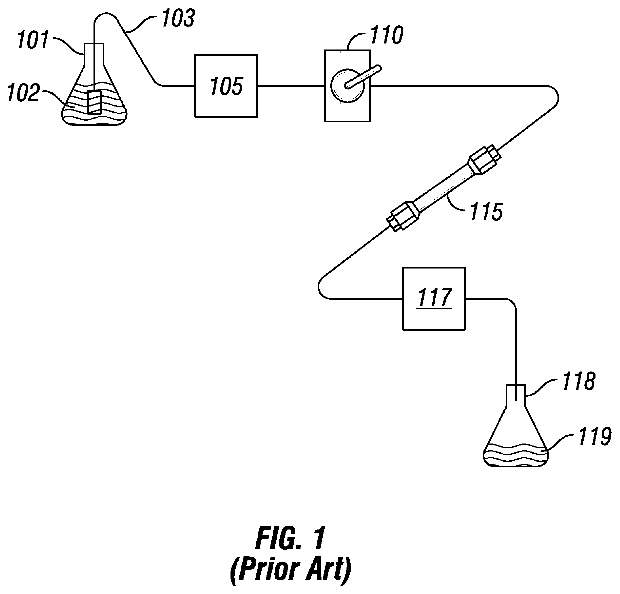
Moreover, the time involved in disconnecting and then connecting a column (or other component) is unproductive because the LC system is not in use and the operator is engaged in plumbing the system instead of preparing samples or other more productive activities.
Hence, the replacement of a column in a conventional LC system involves a great deal of wasted time and inefficiencies.
More recently, however, it has been realized that the use of stainless steel components in a LC system have potential drawbacks in situations involving biological samples.
This presents problems because the detector's measurements (and thus the chromatogram) of a given sample may not accurately reflect the sample if some of the sample's components or ions remain in the tubing, and do not pass the detector.
Perhaps of even greater concern, however, is the fact that ions from the stainless steel tubing may detach from the tubing and flow past the detector, thus leading to potentially erroneous results.
Additionally, ions can easily bind to biological compounds of interest, resulting in changes to the molecules that affect their retention time in the column.
One reason for this is that a valve having a large volume will contain a relatively large volume of liquid, and when a sample is injected into the valve the sample will be diluted, decreasing the resolution and sensitivity of the analytical method.
A stationary phase particle as small as 1 micron is common; the resulting high column packing density leads to substantially increased system pressure at the head of the column.
However, for some types of analyses (e.g., biological testing and metal / ion analysis), stainless steel or other metals are not desired in the fluid path as the metal could interfere with the testing.
Such small inside diameters are typically not available in stainless steel or other high pressure tubing.
The types of fluidic connection systems between the tubes that carry fluids and the ports that receive fluids in these high-pressure applications are limited.
These types of connections sometimes may have drawbacks, however.
For example, the size of cone-shaped fittings and threaded fittings are dependent on the type and size of any given port, which makes quickly interchanging a tube fitted with a particular cone or threaded fitting between various ports difficult.
However, ferrules and lock rings can become deformed after multiple uses (e.g., by connecting, disconnecting, and reconnecting to various ports).
Connection assemblies which attempt to effectuate a seal for high-pressure applications can require a significant amount of torque to effectuate a fluid-tight seal, making the creation of such seals difficult without the use of additional tools and increasing the risk of damage to the fitting assembly or its components due to overtightening.
Moreover, experience suggests that many users do not like to use various tools to connect or disconnect tubing from components such as those in various AI systems.
It is believed that users often apply different amounts of torque to connect or disconnect tubing and the components in such systems, thus resulting in potential problems caused by over-tightening or under-tightening (e.g., leakage or loss of sealing when the fluid is under pressure).
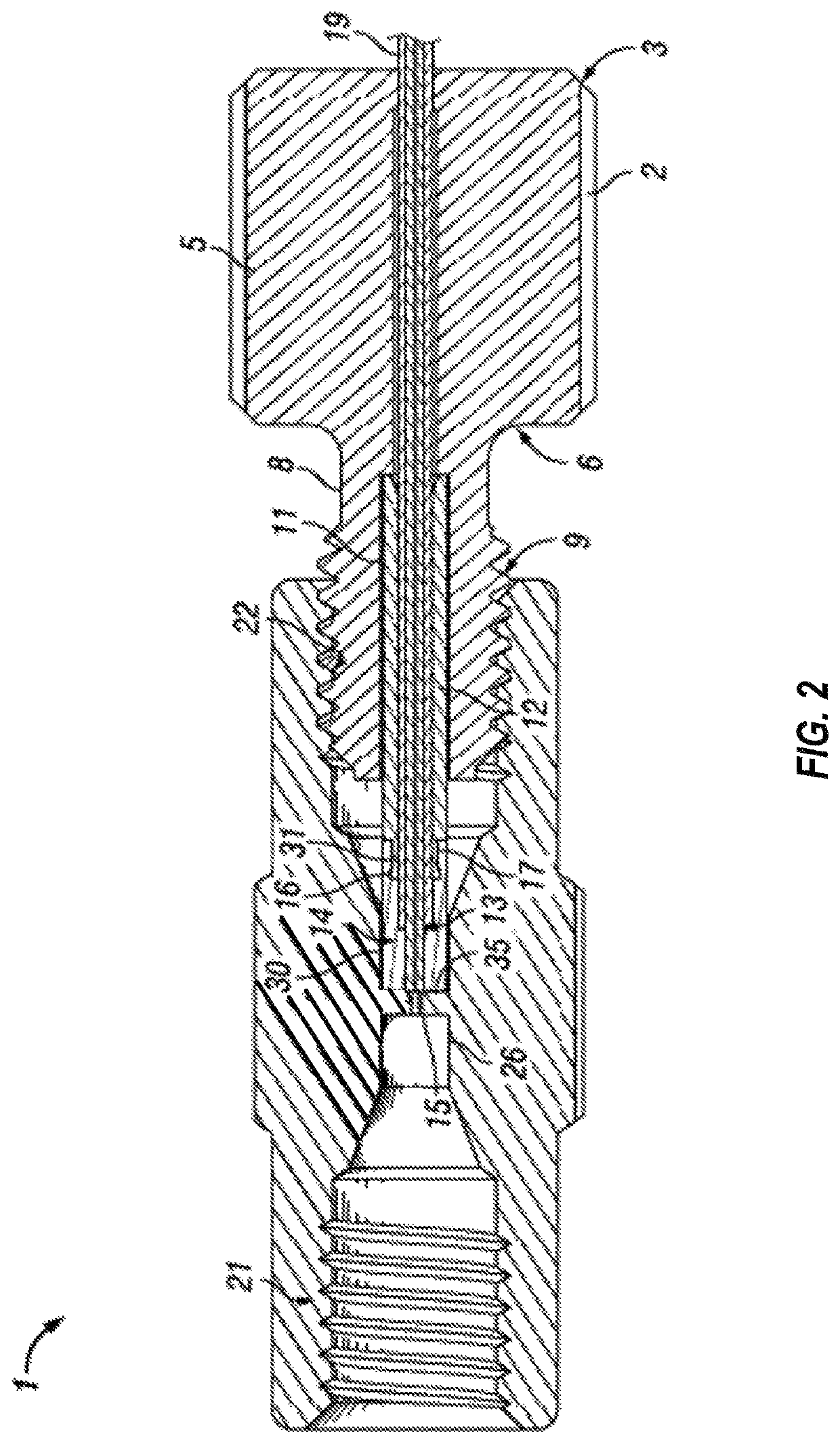
The tube is typically forced into the bottom of the coned port, but there is not currently a mechanism to ensure there is not a gap or space at the port bottom.
The space at the bottom of the port is a concern for those performing liquid chromatography experiments due to the potential to negatively influence the results with carry over and band broadening.
Carry over can produce very unstable results for obvious reasons.
Band broadening is when the peaks identifying a substance become less symmetric and make identification more difficult when peaks of different molecules have similar retention times.
One issue with conventional ferrules used with coned ports is that the torque required to deform / deflect is typically above finger tight levels in order to achieve UHPLC pressures (e.g., above 12,000 psi or so).
End-face seals at such high pressure may require smooth surfaces, however.

Method used


Image

  • Face-sealing fluidic connection system
  • Face-sealing fluidic connection system
  • Face-sealing fluidic connection system

Examples


Embodiment Construction

[0056]In FIG. 1, a block diagram of the essential elements of a conventional liquid chromatography (LC) system is provided. A reservoir 101 contains a solvent or mobile phase 102. Tubing 103 connects the mobile phase 102 in the reservoir 101 to a pump 105. The pump 105 is connected to a sample injection valve 110 which, in turn, is connected via tubing to a first end of a guard column (not shown). The second end of the guard column (not shown) is in turn connected to the first end of a primary column 115. The second end of the primary column 115 is then connected via tubing to a detector 117. After passing through the detector 117, the mobile phase 102 and the sample injected via injection valve 110 are expended into a second reservoir 118, which contains the chemical waste 119. As noted above, the sample injection valve 110 is used to inject a sample of a material to be studied into the LC system. The mobile phase 102 flows through the tubing 103 which is used to connect the variou...


PUM

PropertyMeasurementUnit
fluidic pressureaaaaaaaaaa

Abstract

A tubing or fitting assembly has an inner tube layer, an outer tube layer, a sleeve, a tip portion, and can have a nut. Each of the nut, sleeve, inner and outer tubing layers, and tip portion have a passageway therethrough, with at least the passageways in the sleeve, tip portion, outer tube layer, and nut adapted to allow the inner tube layer to pass therethrough or extend over the inner layer. The tip portion can be molded over an end portion of the inner tube layer and also over a portion of the sleeve. The sleeve may include a retention feature in the form of a lip which extends into the tip portion, and also a narrower portion so that the tip portion and sleeve remain coupled together. The inner and outer tubing layers can also be retained by an interference fit. The ends of the tip portion and inner layer together define a substantially flat surface which can form a seal in a flat-bottomed port of a component such as may be found in any one of a number of components in an analytical instrument system, including for example a liquid chromatography system. The nut, tube, ferrule, and transfer tube or liner tube may comprise biocompatible materials. In addition, the nut may have a slot, such as a slot adapted to allow the tube and the nut to be easily and quickly separated or to allow a portion of the tube to be easily and quickly inserted in the nut.

Description

CROSS-REFERENCE TO RELATED APPLICATIONS[0001]This application claims benefit of priority from U.S. Provisional Patent Application No. 62 / 067,739, filed Oct. 23, 2014, U.S. Provisional Patent Application No. 62 / 127,276, filed Mar. 2, 2015, and U.S. Provisional Patent Application No. 62 / 168,491, filed May 29, 2015, each of which is hereby incorporated by reference herein.FIELD OF THE INVENTION[0002]The present disclosure relates generally to fitting assemblies and fluidic connection systems, such as those used in connecting components of liquid chromatography systems and other analytical instrument systems, and, more specifically, to fitting assemblies and fluidic connection systems for connecting tubing to ports.BACKGROUND OF THE INVENTION[0003]Liquid chromatography (LC) is a well-known technique for separating the constituent elements in a given sample. In a conventional LC system, a liquid solvent (referred to as the “mobile phase”) is introduced from a reservoir and is pumped thro...

Claims


Application Information

Patent Timeline
Patent Type & Authority Patents(United States)
IPC IPC(8): F16L15/08G01N30/60F16L19/02B01D15/10B01L3/00
CPCF16L15/08B01L3/563G01N30/6026B01D15/10F16L19/0206F16L19/0212B01L2300/0838
Inventor GRAHAM, CRAIGBEEMER, ERICELLIS, SCOTTSANDERS, TROYNIENHUIS, NATHANIEL
Owner IDEX HEALTH & SCI
Why Eureka
Try Eureka