
Thin film liquid thermal testing

a thin film, liquid thermal testing technology, applied in the direction of liquid-gas reaction of thin film type, instruments, measurement devices, etc., can solve the problems of special difficulties caused by deposits and increase in number

Active Publication Date: 2020-05-26
TANNAS
View PDF4 Cites 0 Cited by
  • Summary
  • Abstract
  • Description
  • Claims
  • Application Information

AI Technical Summary

Benefits of technology

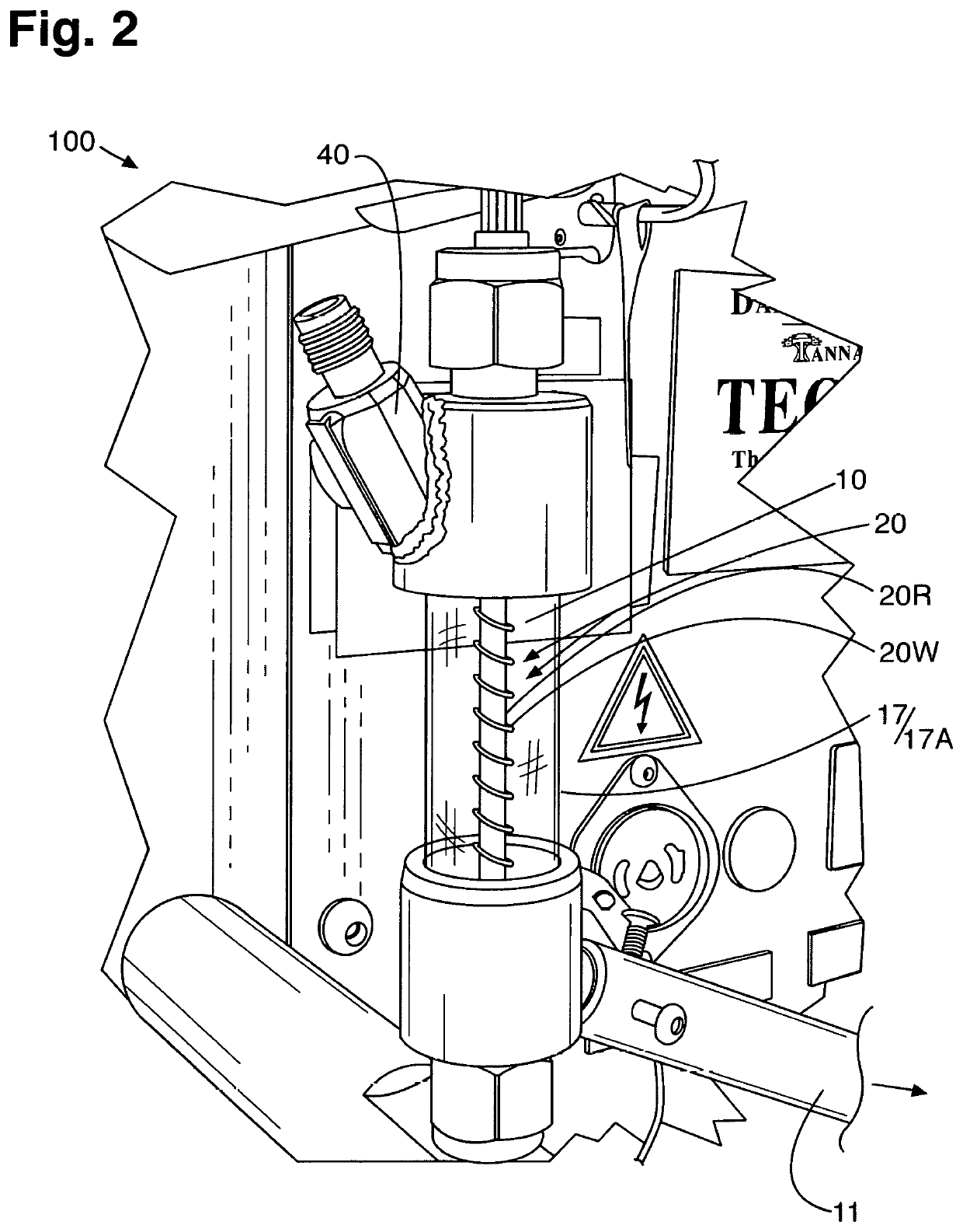
[0011]Provided hereby is apparatus for testing liquid engine oil or other liquid as a test liquid for deposits formed at elevated temperatures under thin-film, reactant / control conditions, which comprises a heatable sample reservoir; a test liquid placement volume; in the test liquid placement volume, a heatable deposit-receiving surface in a form of a rod having a generally helical guide or channel for the test liquid such that a thin film can be formed thereon, in which bulk flow and its inherent difficulties in effective diffusion of a gaseous reactant / control substance into the test liquid can be avoided, and diffusion can be ameliorated or eliminated as a substantially limiting factor when the test liquid is delivered to the heatable deposit-receiving surface by a thin film forming unit, with the heatable deposit-receiving surface in liquid communication with the test liquid placement volume; the thin film forming unit, which can deliver the test liquid to the heatable deposit-receiving surface as the thin film; a reactant / control gas delivery unit; and a supply of at least one reactant / control gas, which may or may not adversely affect the test liquid—wherein the thin film forming unit and the reactant / control gas delivery unit are positioned in an upper reach of the test liquid placement volume so that both the liquid engine oil or other liquid as the test liquid, and the supply of at least one reactant / control gas can be delivered about an upper reach of the heatable deposit-receiving surface, optionally, in addition to or in lieu of which, being delivered to the test liquid away from the heatable deposit-receiving surface in the test liquid placement volume; and a surrounding mantle spaced apart from the heatable deposit-receiving surface a distance substantially non-varying from top to bottom with respect to the heatable deposit-receiving surface. Provided as well is a method for testing liquid engine oil or other liquid as a test liquid for deposits formed at elevated temperatures under thin-film conditions, which comprises steps, not necessarily conducted in series, as follows: providing the apparatus for testing the test liquid for deposits formed at elevated temperatures under thin-film conditions; providing the test liquid; heating the heatable deposit-receiving surface; delivering the test liquid and the supply of at least one reactant / control gas about an upper reach of the heatable deposit-receiving surface for a predetermined time under elevated temperature, thin-film conditions; and checking for and / or assaying any deposit on the heatable deposit-receiving surface.
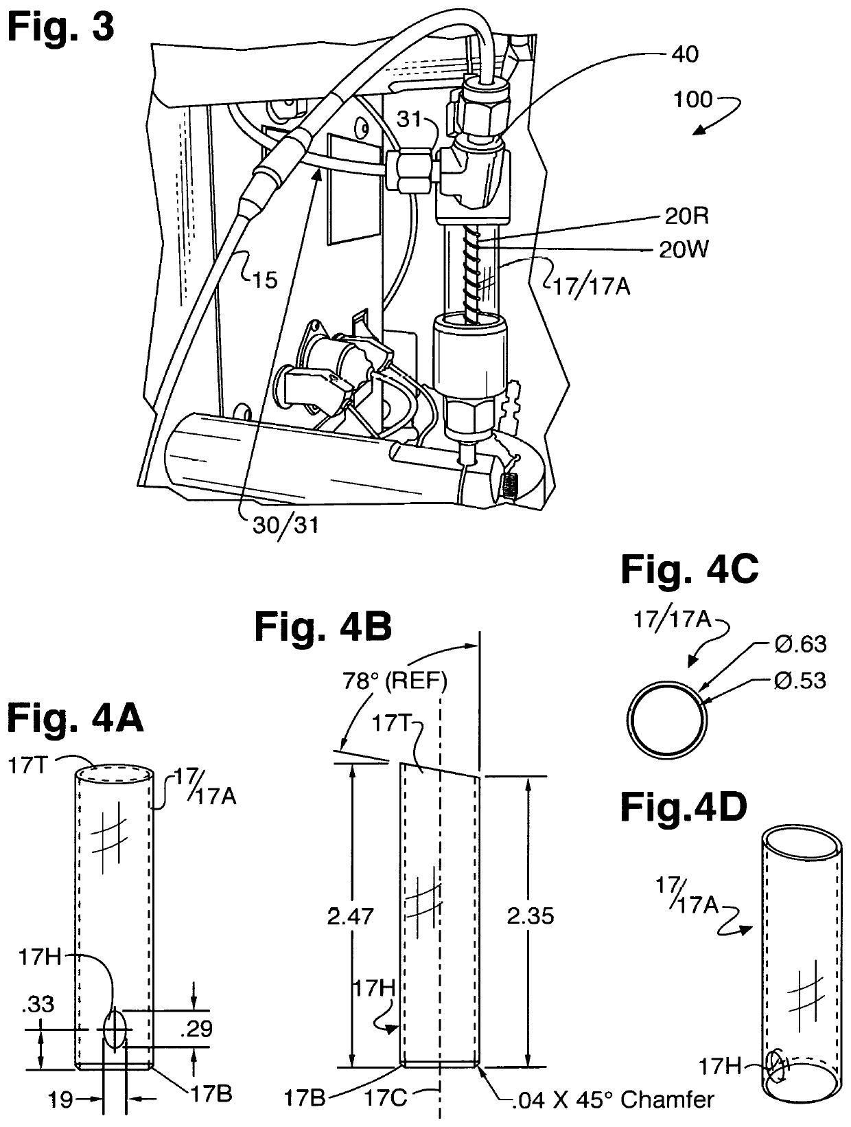
[0013]By the invention, the art is improved in kind and provided an alternative; and one or more of the difficulties, drawbacks, and limitations of the prior art is or are ameliorated or overcome. More reliable test apparatus and methodology is provided for testing for deposits from engine oils, notably to include modern engine oils with their additive packages, which may contain chelated molybdenum and / or other additive(s), especially under modern internal combustion engine turbocharger operating conditions, More particularly, highly accurate, precise, and reliable characterizations of engine oil properties, particularly their propensity for forming turbocharger deposits can be extended to modern, low viscosity, chelated molybdenum containing engine oils, other advanced formulations, and so forth and the like. Thus, predictions can be made better, more efficiently, and more reliably concerning their performance in the field. Collection and measurement of volatiles, which in an engine oil may typically comprise up to about 13% of the oil by weight, can be avoided and not compromise test performance. Furthermore, in particular, in contrast to historical TEOST® 33C turbo deposit testing (ASTM D6335)—where oil is pumped up a simple deposit rod from the bottom, which is found to actually flood the rod and its casing, which results in uncertainty as to whether all of the oil within the casing does or does not come in contact with the rod as the oil is pushed up and then back to the reservoir, and by which modern engine oils form high levels of deposits—it is believed to be critical to expose test oil to the top of the heatable deposit-receiving surface, with maintenance of contact with the oil to the rod for a more extended period of time at temperature(s) and condition(s) more representative of those encountered in a modern internal combustion engine turbocharger area, which is provided, for example, by employment of a deposit rod with helically wound wire about a central portion whereof such as employed in TEOST® MHT® testing. Unlike TEOST® MHT® testing, however, in which a bulbous glass mantle and separation of volatiles is employed, the present surrounding mantle, for example, embodied as a hollow cylindrically walled glass mantle configured generally as a straight tube to be consistently close to the heatable deposit-receiving surface, say, the steel wire-wound deposit rod otherwise employed in the TEOST® MHT® testing, does not allow for separation of lower molecular weight fractions from the test liquid, for example, low molecular weight hydrocarbons and so forth from the test oil. Rather, the present surrounding mantle maintains any lower molecular weight vaporized fraction in close proximity to the heatable deposit-receiving surface. With the present surrounding mantle, the lower molecular weight fractions that may be in a vapor phase condense, for the most part, in a drain tube configured to accommodate this, on their way back to a test liquid reservoir, which advantageously is heated to, say, about from 90° C. to 110° C., for example, about 100° C. The invention is efficient to manufacture and operate, with operator error not compromised.

Problems solved by technology

In general, such apparatus and method addresses milder conditions than turbocharger conditions, say, about from 100° C. to 200° C., with, however, test oil including adversely affecting gas such as moist air and / or nitrous oxide also being pumped from a reservoir, also in bulk flow, up through a tube containing a heated rod, on which deposits form.
In particular, modern low viscosity oils, which can provide for better fuel efficiency and longer engine life, among other things, more and more contain chelated molybdenum compounds as additives, and these present special difficulties from deposits that can form, which are increased in number and varied in character.

Method used


Image

  • Thin film liquid thermal testing
  • Thin film liquid thermal testing
  • Thin film liquid thermal testing

Examples


example 1

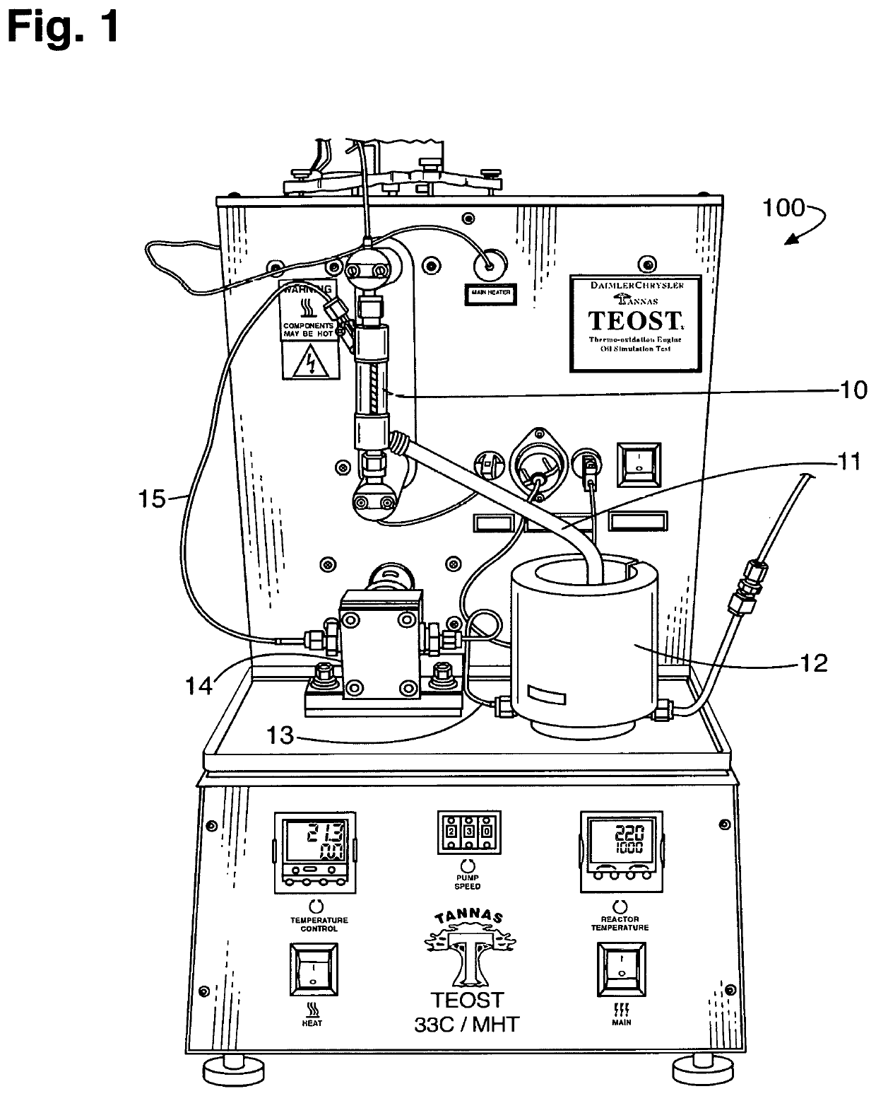
[0037]Apparatus as of FIG. 1 is used to test various reference engine oils on two separate apparatus by two separate groups, Savant R&D (SAV) and Tannas R&D (TAN). A PYREX® glass mantle as in FIGS. 4A-4D is employed with a commercially available TEOST® MHT® steel depositor rod having a steel spring helically wound around its midsection. Oil inlet is at the top of the rod. A ferric naphthenate catalyst (0.44 mg Fe / mL test oil—a 33C catalyst at MHT® test loading) is employed. Thermocouple depth is 9.7 cm. The thermocouple control placed at the desired “hot” spot on the rod, as established by a calibration method, from which the test temperature is maintained. Placing the thermocouple at a specific location ensures good temperature control at that location. The test temperature, which the thermocouple measures, is a constant 285° C., with moist air alone being employed at a 10-mL / minute flow rate. Moist air is used because it mimics normal humid air, which in an operational turbocharge...

example 2

[0041]Reference oils from the list set forth above for use in the examples are tested and benchmarked against standard TEOST® MHT® and TEOST® 33C tests for comparison. In addition to the oils employed in Example 1, another passing oil, Oil B, is employed.

[0042]The reference oils are tested according to the protocol of Example 1, excepting that an 18-hour run time (vs. the 24-hour run time of Example 1) and a temperature of 290° C. for the heatable depositor-receiving surface 20 is employed for the Turbo unit, i.e., for the configuration of the instant invention employed in the present example. For the TEOST® MHT® testing of the same reference oils, both employ only moist air as in Example 1, but otherwise are carried out according to ASTM D7097 and ASTM D6335 standard test methods, respectively. Results are depicted in FIG. 6.

[0043]This shows that ability to differentiate passing oils from failing oils is enhanced in comparison to the legacy tests. Results from the TEOST® MHT® testi...

example 3

[0044]Additionally, reference oils are tested according to the protocol of Example 2. For comparison, those results are benchmarked against TEOST® MHT® testing as a control, and modified TEOST® MHT® testing at a higher temperature of 300° C., both using only the moist air as in Example 2 but otherwise per ASTM D7097. Results are depicted in FIG. 7.

[0045]This shows that deposit levels can be altered from temperature differences under TEOST® MHT® conditions. Also, it is noted that the TEOST® MHT® testing, even at 300° C., does not lead to the extent of separation of the instant invention (Turbo) at 290° C., as deposit levels tend to increase proportionately across all oil types as compared to the preferential separation from the instant invention (Turbo), which employs the cylindrical, straight-wall glass mantle and other features of the instant invention.


PUM

PropertyMeasurementUnit
non-orthogonal angleaaaaaaaaaa
temperatureaaaaaaaaaa

Abstract

Elevated temperature liquid testing apparatus and methodology in which a thin film of test liquid and a reactant / control gas are provided about the top of a depositor member that is surrounded by a special mantle, for example, a substantially cylindrically walled glass mantle. As an oxidative engine oil test, it may mimic turbocharger conditions of a modern internal combustion engine. For example, employing moist air, the apparatus can test a thin film of engine oil for oxidation deposits at a predetermined temperature, say, 285° C., 290° C., or cycled between 285° C. or 290° C. and 320° C. or 330° C.

Description

[0001]This claims benefits under 35 USC 119(e) of provisional patent application No. U.S. 62 / 707,465 filed on Nov. 2, 2017 A.D. The specification of that application, of course to include its drawings, is incorporated herein by reference.FIELD AND PURVIEW OF THE INVENTION[0002]This concerns elevated temperature liquid testing apparatus and methodology in which a thin film of test liquid and a reactant / control gas are provided about the top of a depositor member that is surrounded by a special mantle, for example, a substantially cylindrically walled glass mantle. As an oxidative engine oil test, it may mimic turbocharger conditions. For example, employing moist air, the apparatus can test a thin film of engine oil for oxidation deposits at a predetermined temperature, say, 285° C., 290° C., or cycled between 285° C. or 290° C. and 320° C. or 330° C.BACKGROUND TO THE INVENTION[0003]U.S. Pat. Nos. 5,287,731 and 5,401,661 to Florkowski et al. disclose thermo-oxidation engine oil simula...

Claims


Application Information

Patent Timeline
Patent Type & Authority Patents(United States)
IPC IPC(8): G01N33/28B01J10/02
CPCG01N33/2805G01N33/2817B01J10/02
Inventor EVANS, JONATHAN C.SELBY, THEODORE W.MANNING, MARTAMIILLER, GREGORY C.VANBERGEN, WILLIAM JOHN
Owner TANNAS
Learn More