Inverting temporary valve sheath

a temporary valve and sheath technology, applied in the field of temporary valve and sheath, can solve the problems of prolonged recovery time, cardiopulmonary bypass, and degeneration of human heart valves, and achieve the effect of increasing the time or effort needed to compl

Active Publication Date: 2020-06-02
VALVE MEDICAL
View PDF36 Cites 0 Cited by
  • Summary
  • Abstract
  • Description
  • Claims
  • Application Information

AI Technical Summary

Benefits of technology

[0006]The invention relates to a device comprising a percutaneous temporary valve and sheath having an inverting section for delivery and removal of the percutaneous temporary valve from a target blood vessel. The invention also relates to a percutaneous temporary valve system and method of deployment. The device may be used in percutaneous valve repair procedures, valve replacement procedure or any situation in which native valve function is insufficient. The device may be removed without causing trauma to the vessel or unduly increasing the time or effort needed to complete the procedure. The device may provide temporary hemodynamic support to a patient for various periods of time lasting from seconds to hours and possibly days.

Problems solved by technology

However, human heart valves can degenerate for a variety of reasons.
The standard surgical procedure involves the opening of the patient's thoracic cavity, which is highly invasive and requires cardiopulmonary bypass and a prolonged recovery time.

Method used


Image

  • Inverting temporary valve sheath
  • Inverting temporary valve sheath
  • Inverting temporary valve sheath

Examples


Embodiment Construction

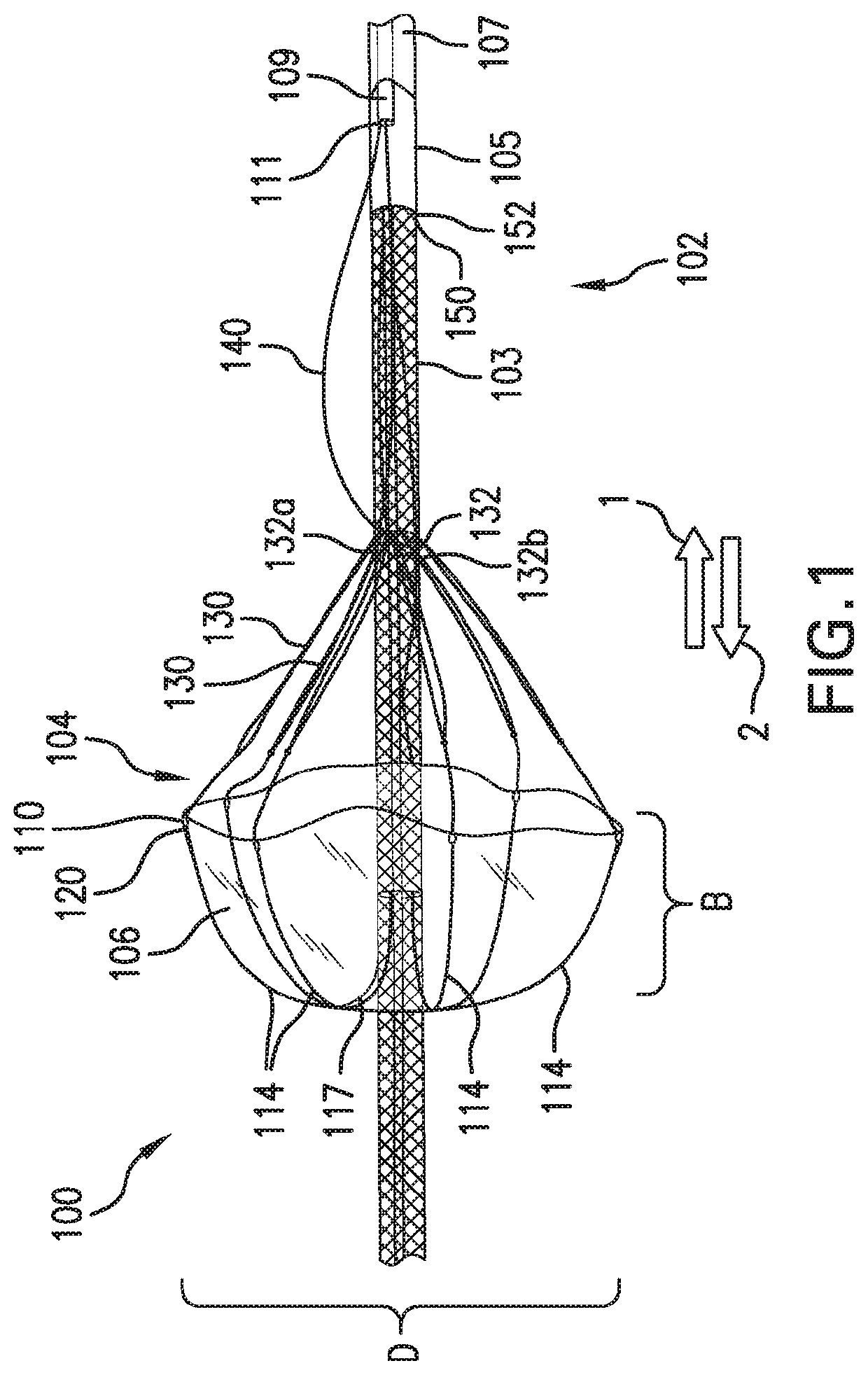
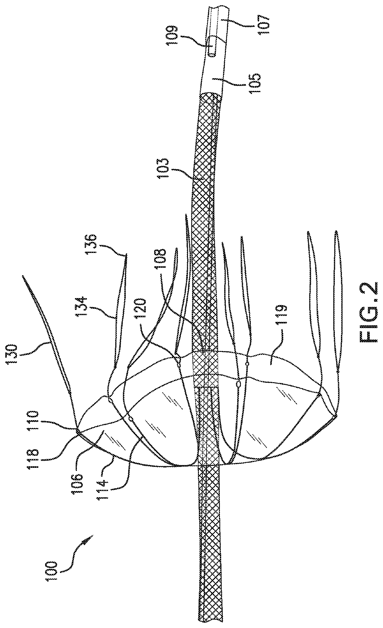
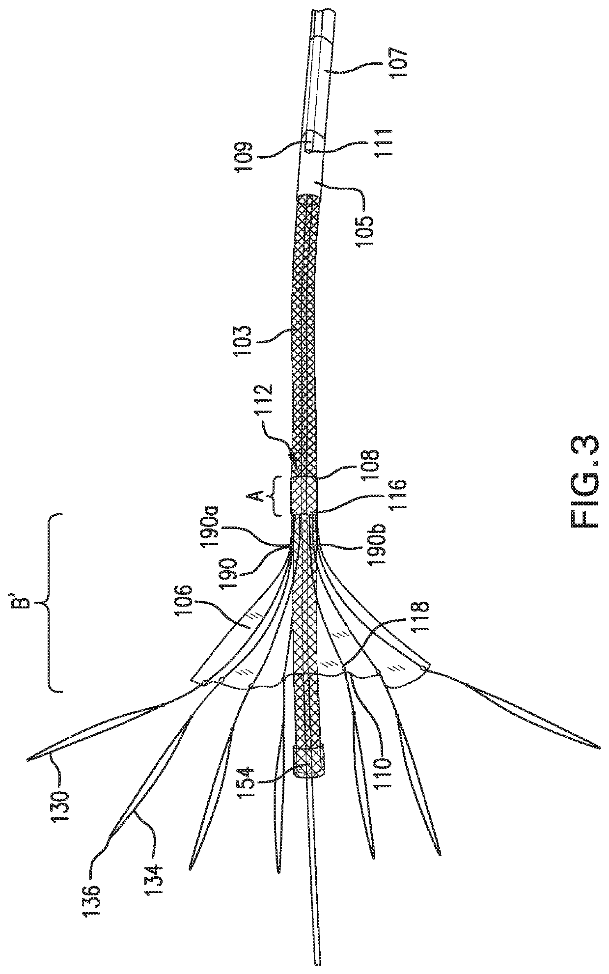
[0023]The invention relates to an inverting sheath and an integrated percutaneous temporary valve for use in intraluminal procedures. The invention also describes a method of delivery and deployment of a percutaneous temporary valve system and methods for its removal.

Device

[0024]A device according to the invention comprises a sheath having a first section located distally of a second section, said first section having a temporary valve attached thereto. In an embodiment of the invention, a first end of the temporary valve is permanently attached to the first section and a second end of the temporary valve is removably attached to the first section by a plurality of lines. In one embodiment, the first section and temporary valve are movable between an inverted or partially inverted configuration for delivery and a radially expanded canopy or umbrella configuration after deployment. Expansion of the canopy from the inverted configuration may be aided by optional ribs in the valve body...


PUM


Abstract

A percutaneous device including a temporary valve attached to a sheath, the sheath having an inverting section for delivery and removal thereof from a blood vessel. The sheath is inverted for delivery, housing the valve between inverted layers thereof. To deploy said valve, the sheath is everted to position the temporary valve on an outer surface thereof. The temporary valve and sheath are reversibly movable between inverted and deployed configurations. Upon eversion, the temporary valve assumes a radially expanded canopy shape having an outer diameter selected to contact the vessel wall and allow blood flow in only one direction. The temporary valve may be removed by releasing one end of the valve from the sheath, flattening the temporary valve along the longitudinal axis of the sheath. Also provided is a temporary valve system comprising a dilator for inverting and everting the sheath, said dilator being removably connected to the sheath.

Description

[0001]This application claims the benefit of priority of U.S. Provisional Application Ser. No. 62 / 336,983 filed May 16, 2016.FIELD OF THE INVENTION[0002]The present invention relates to a temporary valve and sheath for maintaining normal blood flow during percutaneous cardiovascular procedures. The invention also relates to a system comprising an inverting temporary valve device, a method of deploying said device in a living body and a method of removing said device from the body.BACKGROUND OF THE INVENTION[0003]Valves are important structures in the human heart because they maintain blood flow in a single direction with minimal pressure loss. However, human heart valves can degenerate for a variety of reasons. For example, a malfunctioning heart valve may be stenotic, where the leaflets of the valve do not open fully, or the valve may be regurgitant, where the leaflets of the valve do not close properly, or a combination of both. Valve repair and replacement procedures have thus be...

Claims


Application Information

Patent Timeline
Patent Type & Authority Patents(United States)
IPC IPC(8): A61F2/24A61F2/95
CPCA61F2/2427A61F2/2436A61F2/2439A61F2/2412A61F2250/0059A61F2002/9528A61B17/1204A61B17/12036A61B17/12109A61B17/12122A61B17/12131A61B2017/1205
Inventor RICHTER, YORAMWEISZ, ETYKREIZER, MARK
Owner VALVE MEDICAL
Why Eureka
Try Eureka