
Liquid crystal display

a liquid crystal display and display technology, applied in the field of lcd devices, can solve the problems of rc delay, unavoidable flicker problem of conventional large-size lcd devices, and increase the cost of manufacturing and time, and achieve the effect of reducing power consumption, simple implementation, and reducing manufacturing costs and tim

Active Publication Date: 2013-01-22
INNOLUX CORP
View PDF8 Cites 0 Cited by
  • Summary
  • Abstract
  • Description
  • Claims
  • Application Information

AI Technical Summary

Benefits of technology

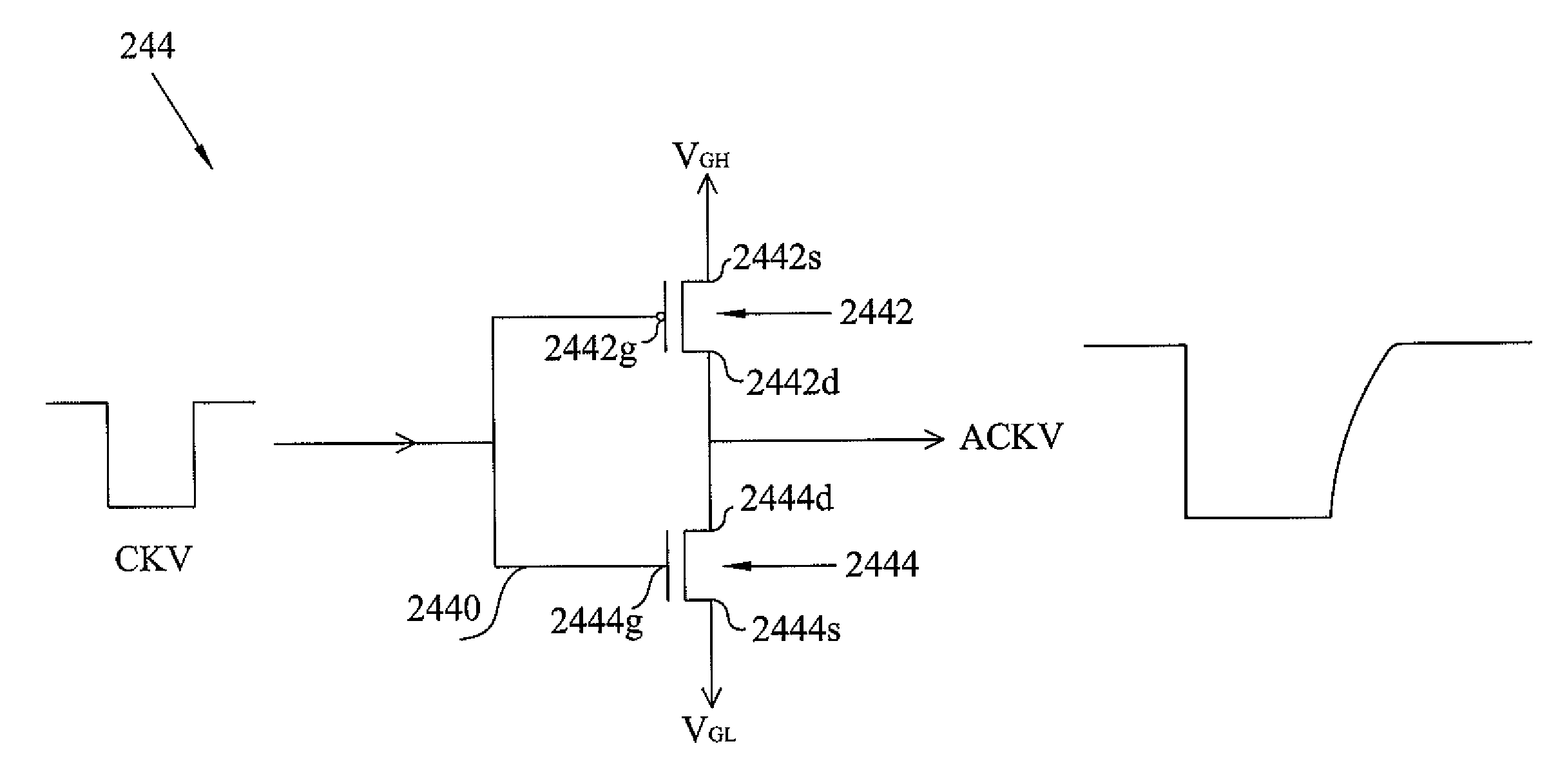
[0008]One aspect of the invention is to provide a LCD device, in which the clock signal, to be received by the gate driving circuit, is adjusted to have the desired waveform. Another aspect is to adopt a CMOS inverter to adjust the waveform of the clock signal. Therefore, the present invention has some advantages such as simple implementation and lower power consumption, without increasing the manufacture cost and time.

Problems solved by technology

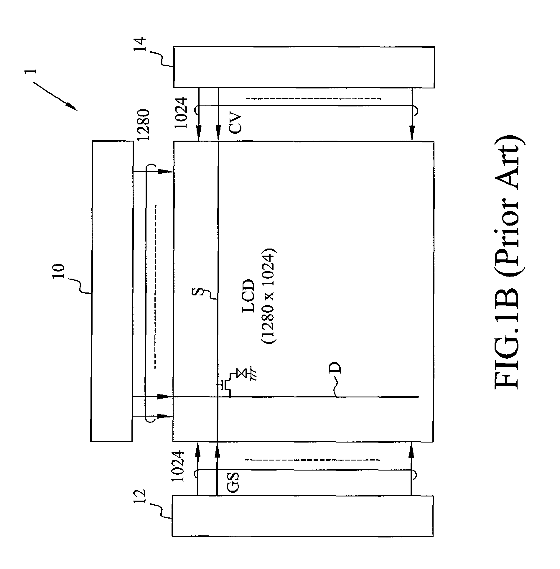
However, conventional large-size LCD devices unavoidably suffer from the “flicker” problem, which becomes more serious with the size of LCD panel.
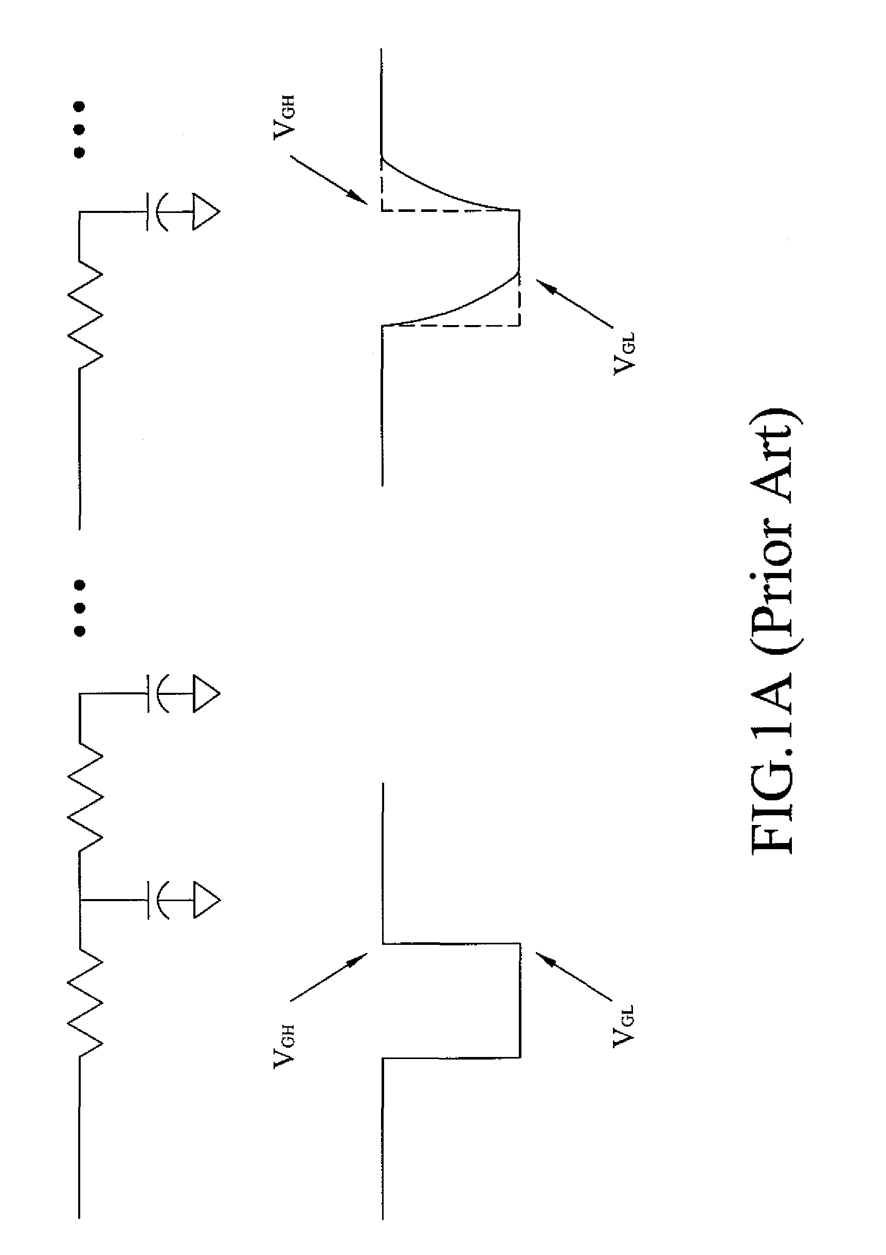
However, parasitic capacitors / resistors on the scan line, resulting from the manufacture process, will result in RC delay and distort the waveform of the gate driving signal, as shown in FIG. 1A.
The distortion becomes more serious when the gate driving signal goes to the rear parts of the scan line.
Although they can shape the gate driving signal, the variable voltage source will consume more power.
Moreover, conventional solutions will make the circuit implementation complicated and increase the manufacture cost.

Method used


Image

  • Liquid crystal display
  • Liquid crystal display
  • Liquid crystal display

Examples


Embodiment Construction

[0020]FIG. 2A schematically show a LCD device 20 according to an embodiment of the invention. The LCD device 20 could be embedded in a mobile phone, a digital still-picture camera, a car navigation system, a mobile DVD-player, a gaming device, or a hand-held consumer appliance, a television, a computer monitor, a large-screen consumer electronics device, or a professional appliance. In the embodiment, the LCD device 20 includes a power supply 250 and a LCD panel 200 having the clock circuit 240. The power supply 250 is connected to the LCD panel 200 to supply power to the LCD panel 200. Note that the dimensional and the scale and the relative positions of elements in the drawings are used to explain the invention, but should not be construed in a limiting sense.

[0021]The LCD device 20 includes LCD panel 200. As further shown in FIG. 2B, the panel 200 includes a TFT array 210, a gate driving circuit 220, a data driving circuit 230, and a clock circuit 240. The gate driving circuit 22...


PUM


Abstract

A liquid crystal display (LCD) device is provided. The LCD device includes a LCD panel, which further includes a plurality of scan lines, a gate driving circuit, a clock circuit. The clock circuit includes a clock generator and an adjusting circuit. The clock generator generates a clock signal having a first high voltage level and a first low voltage level. The adjusting circuit, coupled to the clock generator, receives the clock signal and generates an adjusted clock signal having the same period as the clock signal. The adjusted clock signal has a second high voltage level and a second low voltage level. The gate driving circuit, coupled to the clock circuit, receives the adjusted clock signal as a gate driving signal in order to drive the scan lines.

Description

CROSS REFERENCE TO RELATED APPLICATIONS[0001]This application claims the right of priority based on Taiwan Patent Application No. 097126929 entitled “Liquid Crystal Display”, filed on Jul. 16, 2008, which is incorporated herein by reference and assigned to the assignee herein.FIELD OF INVENTION[0002]The invention relates to a LCD device, particularly to a LCD device adopting Low-Temperature Poly-Si Thin Film Transistors (LTPS TFT).BACKGROUND OF THE INVENTION[0003]LCD devices have several advantages and thus are generally adopted in the portable information products such as mobile phones, laptops, PDA, etc. However, conventional large-size LCD devices unavoidably suffer from the “flicker” problem, which becomes more serious with the size of LCD panel.[0004]Generally, a LCD device has a LCD panel, wherein a gate driving circuit provides gate driving signals to turn on the TFTs on the scan line. Typically the gate driving signal is square-wave signal. However, parasitic capacitors / resi...

Claims


Application Information

Patent Timeline
Patent Type & Authority Patents(United States)
IPC IPC(8): G09G3/36
CPCG09G3/3611G09G2310/0289G09G2310/066G09G2310/08G09G2320/0223G09G2320/0247G09G2330/021
Inventor JIANG, JIAN-XUNCHIU, CHANG MING
Owner INNOLUX CORP
Learn More