Application control system and application control method
an application control and image capture technology, applied in the field of image capture system and application control method, can solve the problems of insufficient safety and operability of application control over the image capture device by the application server, and achieve the effect of improving the safety and operability of application control, realizing safely and easily for users
- Summary
- Abstract
- Description
- Claims
- Application Information
AI Technical Summary
Benefits of technology
Problems solved by technology
Method used
Image
Examples
first exemplary embodiment
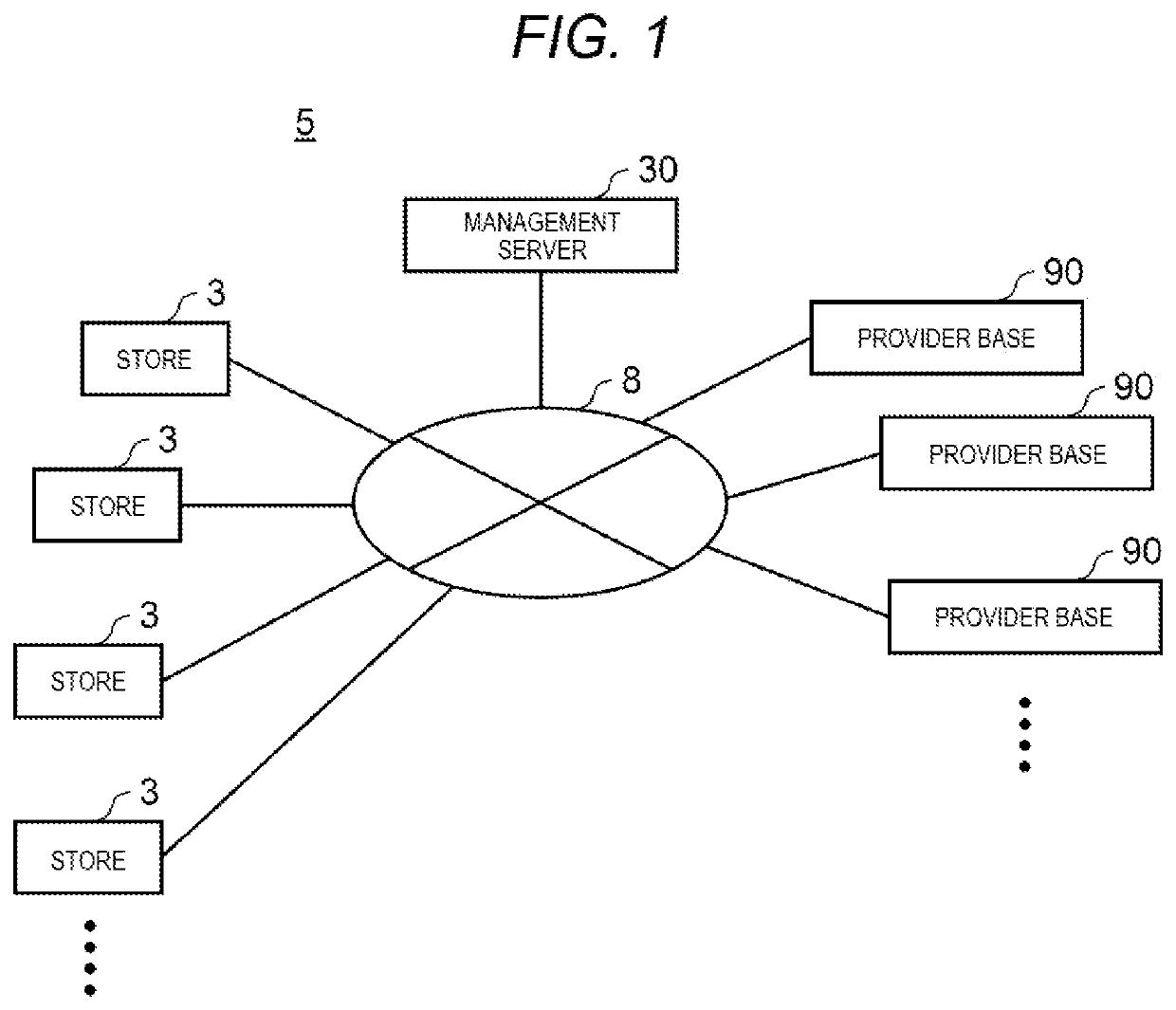
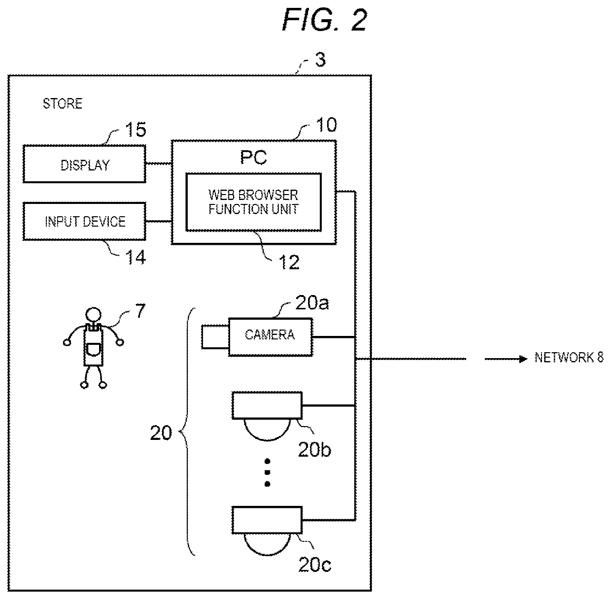
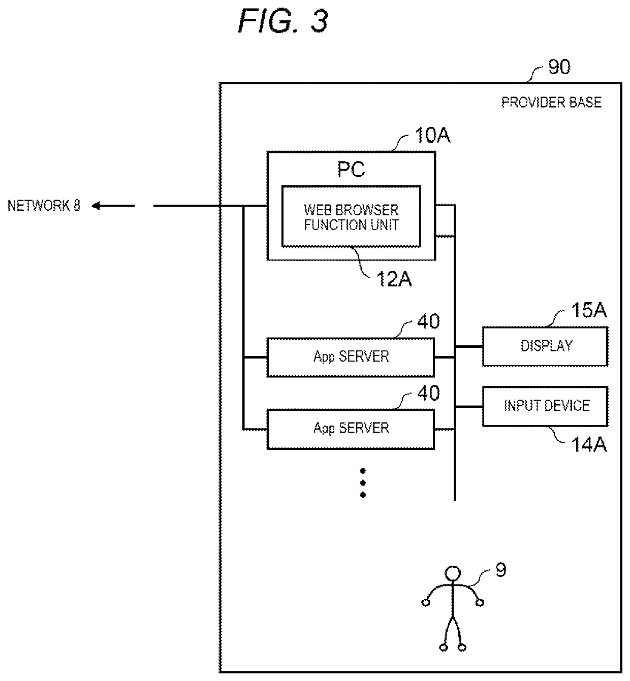
[0056]FIG. 1 is a schematic diagram showing a configuration example of camera system 5 in a first exemplary embodiment. FIG. 2 is a schematic diagram showing a configuration example of each device disposed in store 3. FIG. 3 is a schematic diagram showing a configuration example of each device disposed in provider base 90.
[0057]Camera system 5 includes each device disposed in management server 30, each device disposed in store 3, and each device disposed in provider base 90. For example, PC 10, input device 14, display 15, and one or more cameras 20a, 20b, and 20c are disposed in store 3. For example, PC 10A, input device 14A, display 15A, and one or more application (App) server 40 are disposed in provider base 90. Incidentally, the numbers of cameras and App servers 40 are not limited to the examples of FIG. 1 to FIG. 3.
[0058]In camera system 5, for example, plural types of cameras 20a, 20b, and 20c, and PC 10 placed in store 3 are connected to network 8 such as the Internet. When...
second exemplary embodiment
[0247]The first exemplary embodiment illustrates that App server 40 (CamApp management unit 41 of App server 40) retains a CamApp Package including CamApp. The second exemplary embodiment illustrates that management server 30A retains a CamApp Package including CamApp.
[0248]In camera system 5A of the second exemplary embodiment, the same reference numerals are used for the same components as those of camera system 5 of the first exemplary embodiment, and the explanation thereof will be omitted or simplified. The configuration of each apparatus in the present exemplary embodiment is the same as that in the first exemplary embodiment.
[0249]FIG. 21 is a block diagram illustrating a configuration example of camera 20A.
[0250]Camera 20A includes, for example, a CPU or a DSP, and a ROM or RAM. The CPU or the DSP executes various programs (for example, an OS, a middleware program, and an application program) retained in the ROM or the RAM to realize various functions of camera 20A. Camera 2...
third exemplary embodiment
[0343]Although the first and second exemplary embodiments exemplify the application control for cameras 20 and 20A, as in the third embodiment, the same may apply to the application control for terminal device 200 other than cameras 20 and 20A. That is, the contents of the first and second exemplary embodiments may be changed into contents in which camera 20 is replaced with terminal device 200. Further, camera 20 and terminal device 200 may be mixed.
[0344]In the third exemplary embodiment, in place of camera systems 5 and 5A, monitoring system 5B (not shown) is assumed. Comparing monitoring system 5B with camera systems 5 and 5A according to the first and second exemplary embodiments, monitoring system 5B is the same as camera systems 5 and 5A except for including terminal device 200 instead of camera 20. Monitoring system 5B may include terminal device 200 and camera 20.
[0345]FIG. 32 is a schematic diagram showing an example of arrangement of terminal devices 200 in store 3. Examp...
PUM
 Abstract
Description
Claims
Application Information
 - R&D
- Intellectual Property
- Life Sciences
- Materials
- Tech Scout
- Unparalleled Data Quality
- Higher Quality Content
- 60% Fewer Hallucinations
Browse by: Latest US Patents, China's latest patents, Technical Efficacy Thesaurus, Application Domain, Technology Topic, Popular Technical Reports.
© 2025 PatSnap. All rights reserved.Legal|Privacy policy|Modern Slavery Act Transparency Statement|Sitemap|About US| Contact US: help@patsnap.com


