Image capture system and application control method

a capture system and image technology, applied in the direction of digital transmission, program/content distribution protection, instruments, etc., can solve the problems of insufficient safety and operability of application control over the image capture device by the application server, and achieve the effect of improving the safety and operability of application control, realizing safely and easily for users

Active Publication Date: 2018-06-07
VIEUREKA CORP
View PDF0 Cites 5 Cited by
  • Summary
  • Abstract
  • Description
  • Claims
  • Application Information

AI Technical Summary

Benefits of technology

[0013]According to the present disclosure, it is possible to improve the safety and operability of application control, by a control device that makes a control request for an applica...

Problems solved by technology

In this case, with the techniques described in PTLs 1 to 3, the safety and operability o...

Method used


Image

  • Image capture system and application control method
  • Image capture system and application control method
  • Image capture system and application control method

Examples


first exemplary embodiment

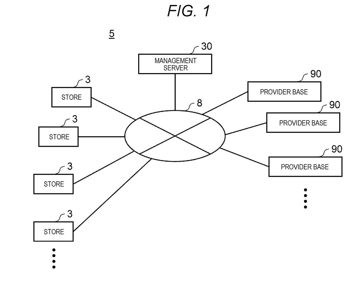
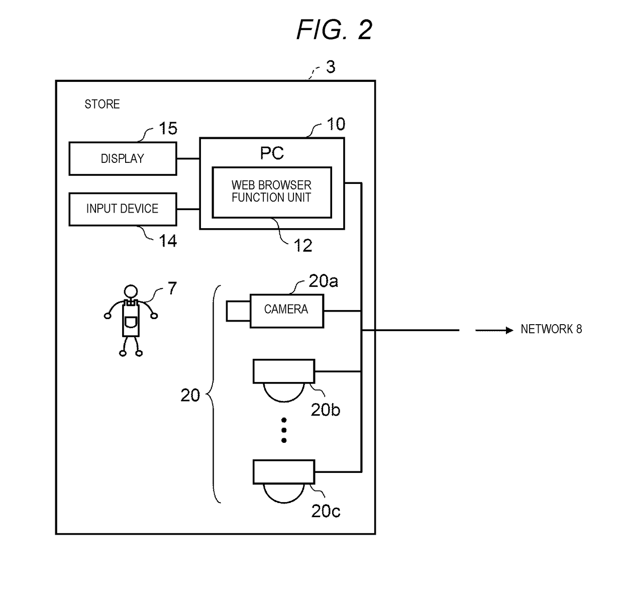
[0054]FIG. 1 is a schematic diagram showing a configuration example of camera system 5 in a first exemplary embodiment. FIG. 2 is a schematic diagram showing a configuration example of each device disposed in store 3. FIG. 3 is a schematic diagram showing a configuration example of each device disposed in provider base 90.

[0055]Camera system 5 includes each device disposed in management server 30, each device disposed in store 3, and each device disposed in provider base 90. For example, PC 10, input device 14, display 15, and one or more cameras 20a, 20b, and 20c are disposed in store 3. For example, PC 10A, input device 14A, display 15A, and one or more application (App) server 40 are disposed in provider base 90. Incidentally, the numbers of cameras and App servers 40 are not limited to the examples of FIG. 1 to FIG. 3.

[0056]In camera system 5, for example, plural types of cameras 20a, 20b, and 20c, and PC 10 placed in store 3 are connected to network 8 such as the Internet. When...

second exemplary embodiment

[0243]The first exemplary embodiment illustrates that App server 40 (CamApp management unit 41 of App server 40) retains a CamApp Package including CamApp. The second exemplary embodiment illustrates that management server 30A retains a CamApp Package including CamApp.

[0244]In camera system 5A of the second exemplary embodiment, the same reference numerals are used for the same components as those of camera system 5 of the first exemplary embodiment, and the explanation thereof will be omitted or simplified. The configuration of each apparatus in the present exemplary embodiment is the same as that in the first exemplary embodiment.

[0245]FIG. 21 is a block diagram illustrating a configuration example of camera 20A.

[0246]Camera 20A includes, for example, a CPU or a DSP, and a ROM or RAM. The CPU or the DSP executes various programs (for example, an OS, a middleware program, and an application program) retained in the ROM or the RAM to realize various functions of camera 20A. Camera 2...


PUM


Abstract

Provided is an image capture system capable of improving the safety and operability of application control, by a control device that makes a control request for an application, over an image capture device. The image capture system includes an image capture device and a management device that manages control over an application for the image capture device, which are connected with each other through a network. The management device generates a control authority based on the contract relating to the application for the image capture device and the image capture device, transmits image capture device identification information relating to the contract, to a control device, acquires the control request and the image capture device identification information from the control device, determines whether or not the control device has the control authority, based on the image capture device identification information, and transmits the control request to the image capture device identified by the image capture device identification information, in a case where the control device has the control authority. The image capture device receives the control request from the management device, and controls the application for the image capture device, in response to the control request.

Description

TECHNICAL FIELD[0001]The present disclosure relates to an image capture system and an application control method.BACKGROUND ART[0002]In the related art, when an application is installed in a device (execution device) that executes an application, a server (storage server) manages an application program and an application package (hereinafter, simply referred to as an application), and the storage server may supply the application to the execution device. The execution device installs and executes the supplied application.[0003]As a system handling an application in the related art, it has been known that in a multifunction peripheral in which a license file is embedded, if the license file is passed to the server and is designated according to the user's operation, the server installs an application in the multifunction peripheral by using the designated license file (for example, see PTL 1).[0004]Further, it has been known that an external terminal, an internal terminal, and an app...

Claims


Application Information

Patent Timeline
IPC IPC(8): H04L29/06H04L9/32G06F21/12G06F9/445G06F21/44G06F21/62
CPCH04L63/062H04L9/3273G06F21/12G06F9/445G06F21/44G06F21/629G06F21/10G09C5/00H04L63/0869
Inventor WAKAI, RYOHEI
Owner VIEUREKA CORP
Why Eureka
Try Eureka