Rhythm shaker

a rhythm shaker and shaker technology, applied in the field of musical instruments, can solve the problems of single tone or timbre or type of sound produced by a single rhythm shaker

Active Publication Date: 2020-06-30
SNYDER ALAN T
View PDF1 Cites 2 Cited by
  • Summary
  • Abstract
  • Description
  • Claims
  • Application Information

AI Technical Summary

Problems solved by technology

Thus, a disadvantage present with the rhythm shakers known in the art is that only a single tone or timbre or type of sound may be produced by a single rhythm shaker.

Method used


Image

  • Rhythm shaker
  • Rhythm shaker
  • Rhythm shaker

Examples


Embodiment Construction

[0018]In the following description, certain specific details are set forth in order to provide a thorough understanding of various disclosed embodiments. However, one skilled in the relevant art will recognize that embodiments may be practiced without one or more of these specific details, or with other methods, components, materials, etc. In other instances, well-known materials, structures and methods associated with vehicles have not been shown or described in detail, to avoid unnecessarily obscuring descriptions of the embodiments.

[0019]Unless the context requires otherwise, throughout the specification and claims which follow, the word “comprise” and variations thereof, such as, “comprises” and “comprising” are to be construed in an open, inclusive sense, that is as “including, but not limited to.”

[0020]Reference throughout this specification to “one embodiment” or “an embodiment” means that a particular feature, structure or characteristic described in connection with the embo...


PUM


Abstract

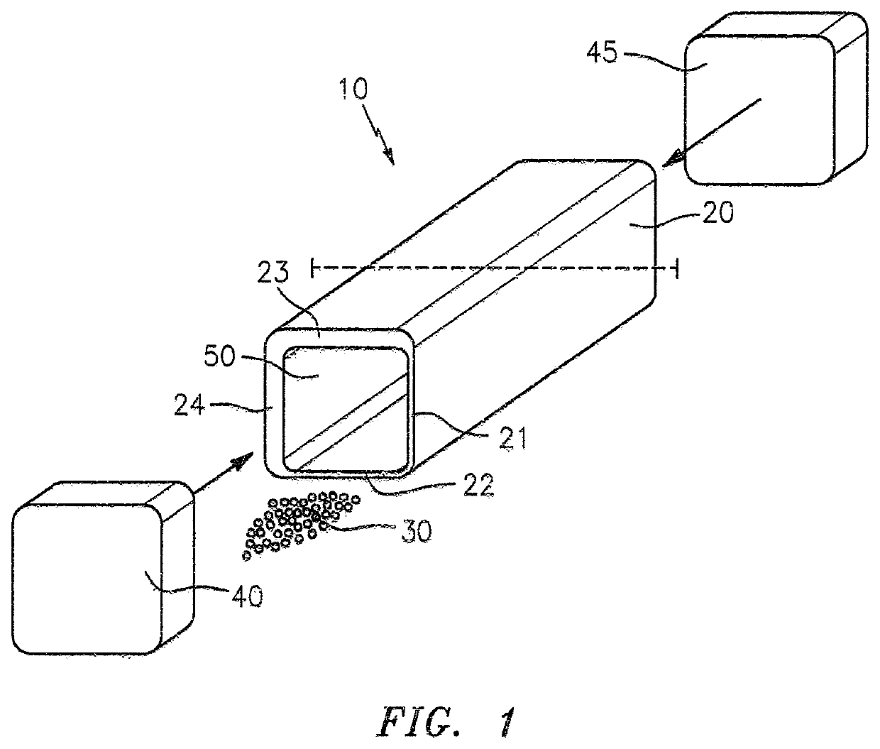
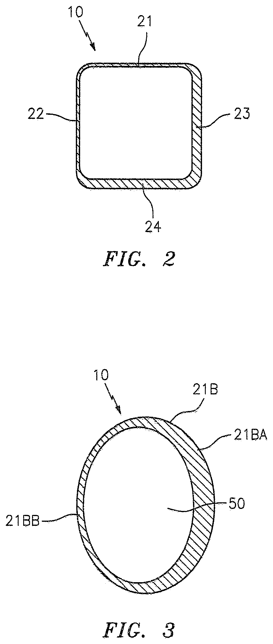
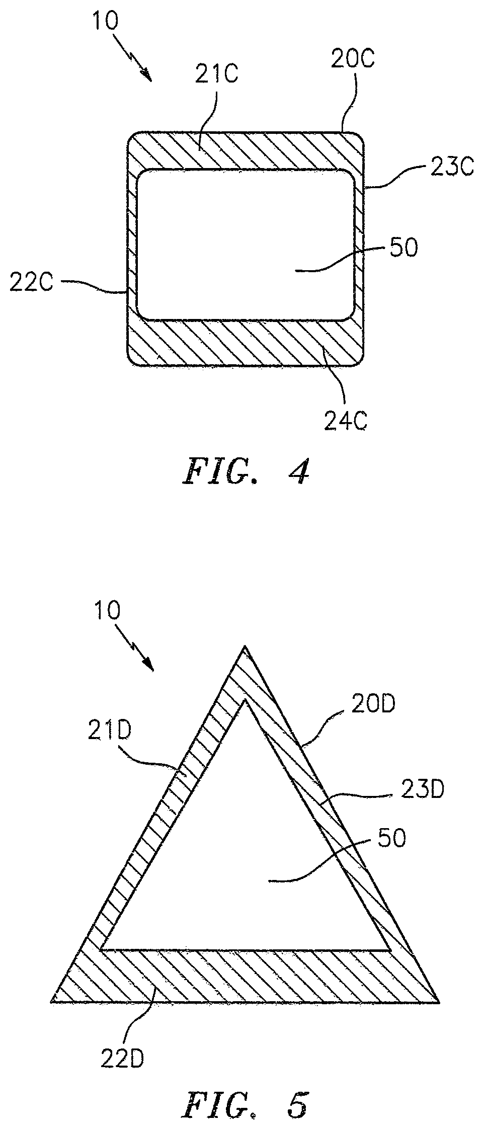
There is provided a rhythm shaker for producing percussive sound. The shaker has a shell that envelops a hollow interior that contains a number of percussive particles. The rhythm shaker's shell has an internal surface on which the enclosed sound producing material can strike the shell and make a sound where the sidewalls of the shell have at least two different thicknesses which, when struck by the enclosed sound producing material, produces a different sound depending on the thickness of the shell where struck.

Description

TECHNICAL FIELD[0001]The present disclosure relates to musical instruments. In particular, the present invention relates to a percussion instrument known as a shaker, a musical shaker, or rhythm shaker.DESCRIPTION OF THE RELATED ART[0002]Rhythm shakers in various forms are often used in the rhythm sections of orchestras and other musical groups to establish rhythm or to provide musical texture in musical performances. Rhythm shakers are used into virtually every form of music.[0003]A typical rhythm shaker is a hollow container or shell, having a number of relatively small percussive media, such as metal shot, plastic beads, seeds or small stones, contained therein. The percussive media occupies a relatively small proportion of the internal volume of the rhythm shaker. A rhythm shaker is operated by shaking it back and forth or around. As such, when the rhythm shaker is operated in this manner, the percussive media through inertia, hits the inside surface of the container or shell wh...

Claims


Application Information

Patent Timeline
Patent Type & Authority Patents(United States)
IPC IPC(8): G10D13/06
CPCG10D13/06G10D13/22G10D13/24
Inventor SNYDER, ALAN T.
Owner SNYDER ALAN T
Why Eureka
Try Eureka