
Reclining high-leg seating unit

a seating unit and high-leg technology, applied in the field of reclining seating units, can solve the problems of improper positioning of cushions, unsuitable reclining mechanisms for certain chair styles,

Active Publication Date: 2020-07-14
ULTRA MEK
View PDF107 Cites 5 Cited by
  • Summary
  • Abstract
  • Description
  • Claims
  • Application Information

AI Technical Summary

Benefits of technology

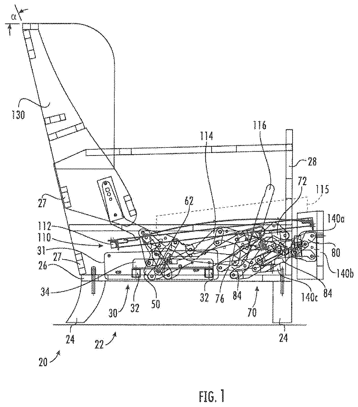
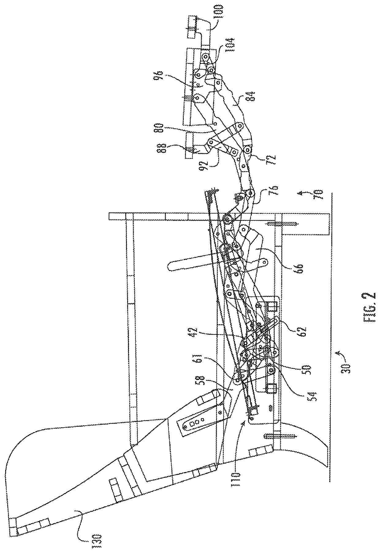
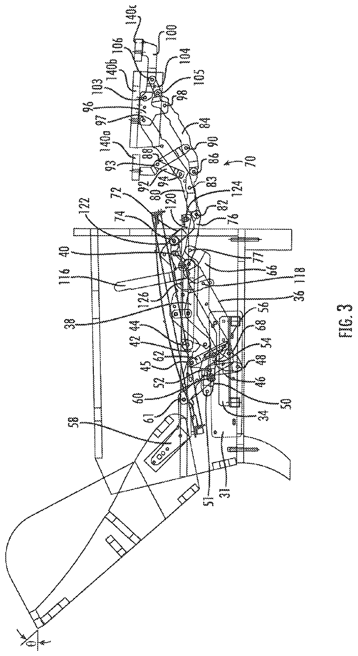
The invention is an elevated mount chair with reclining and footrest mechanisms that allow the chair to move between different positions. The chair has a T-cushion with lateral wings that are positioned forward of the arms. The reclining and footrest mechanisms are made up of a plurality of pivotally interconnected links that move the chair smoothly between the upright, TV, and fully reclined positions. In the upright position, the chair remains stable, while in the TV and fully reclined positions, the chair experiences a slight forward or rearward movement. The chair is designed to provide maximum comfort and stability during use.

Problems solved by technology

Nevertheless, some reclining mechanisms are not well-suited for certain chair styles.
If the recliner chair is configured such that the seat moves rearwardly relative to the arms when moving to the TV or reclined positions, the wings on the T-cushion can catch on the front of the arms prevent the cushion from moving with the seat, such that the cushion is improperly positioned relative to the backrest.
It is ordinarily undesirable for portions of a reclining mechanism to be visible in the space below the chair when the chair is in the upright position, so the designers are faced with providing a reclining mechanism that folds into a relatively small package.

Method used


Image

  • Reclining high-leg seating unit
  • Reclining high-leg seating unit
  • Reclining high-leg seating unit

Examples


Embodiment Construction

[0026]The present invention now is described more fully hereinafter with reference to the accompanying drawings, in which embodiments of the invention are shown. This invention may, however, be embodied in many different forms and should not be construed as limited to the embodiments set forth herein; rather, these embodiments are provided so that this disclosure will be thorough and complete, and will fully convey the scope of the invention to those skilled in the art.

[0027]Like numbers refer to like elements throughout. In the figures, the thickness of certain lines, layers, components, elements or features may be exaggerated for clarity. Broken lines illustrate optional features or operations unless specified otherwise.

[0028]The terminology used herein is for the purpose of describing particular embodiments only and is not intended to be limiting of the invention. As used herein, the singular forms “a”, “an” and “the” are intended to include the plural forms as well, unless the c...


PUM


Abstract

An elevated mount chair includes: a base; a pair of arms; a seat positioned above the base between the arms; a backrest; a first ottoman; a reclining mechanism attached to the base, the seat and the backrest; and a footrest mechanism attached to the seat and the first ottoman, the footrest mechanism being coupled to the reclining mechanism. The seat includes a T-cushion positioned above a seat frame, the T-cushion having lateral wings that are positioned forward of the arms. The reclining and footrest mechanisms comprise a plurality of pivotally interconnected links configured to move the chair between an upright position, a TV position, and a fully reclined position. In moving between the upright, TV and fully reclined positions, a front portion of the seat experiences substantially no forward or rearward movement relative to the arms.

Description

RELATED APPLICATION[0001]This application claims priority from and the benefit of U.S. Provisional Patent Application No. 62 / 450,885, filed Jan. 26, 2017, the disclosure of which is hereby incorporated herein in its entirety.FIELD OF THE INVENTION[0002]The present invention relates generally to seating units, and relates more particularly to reclining seating units.BACKGROUND OF THE INVENTION[0003]Conventionally, a recliner chair will move from an upright position, in which the backrest is generally upright, to one or more reclined positions, in which the backrest pivots to be less upright. The movement of the seating unit between the upright and reclined positions is typically controlled by a pair of synchronized reclining mechanisms that are attached to the seat, backrest and base of the chair. Many recliners will have an extendable footrest that provides support for the occupant's feet in the reclined position.[0004]One particularly popular recliner is the “three-way” recliner, w...

Claims


Application Information

Patent Timeline
Patent Type & Authority Patents(United States)
IPC IPC(8): A47C1/02A47C1/035A47C1/032A47C1/024A47C1/0355A47C3/025A47C3/18A47C1/034A47C3/02
CPCA47C3/18A47C3/0255A47C1/0345A47C3/02
Inventor MURPHY, MARCUS L.
Owner ULTRA MEK
Learn More