
Steering device

a steering device and steering column technology, applied in the direction of steering column, steering parts, vehicle components, etc., can solve the problems of large variation in load at the time of the collapse stroke, and achieve the effect of suppressing load variation, stabilizing impact absorption load, and restricting the inner column

Active Publication Date: 2020-08-11
YAMADA MANUFACTURING CO LTD
View PDF18 Cites 1 Cited by
  • Summary
  • Abstract
  • Description
  • Claims
  • Application Information

AI Technical Summary

Benefits of technology

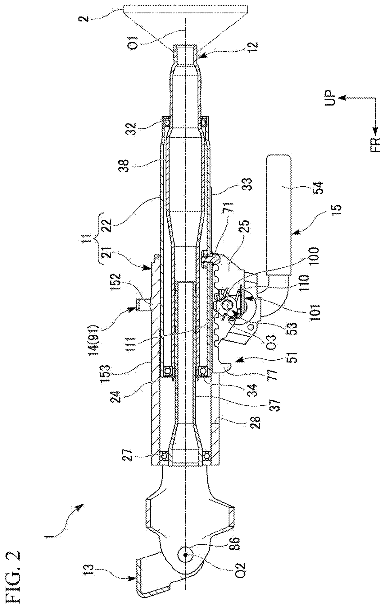
[0012]In the case of the steering device according to the aspect, when the telescopic restricting portion and the telescopic stopper come into contact with each other at the time of a collapse stroke, the telescopic stopper rotates in the withdrawal direction in which the telescopic stopper is withdrawn from the telescopic restricting portion. Therefore, it is possible to suppress a bumping load that is generated due to contact between the telescopic restricting portion and the telescopic stopper and to alleviate a variation in load at the time of the collapse stroke. Accordingly, it is possible to efficiently alleviate an impact load over the entire collapse stroke and thus it is possible to achieve an improvement in impact absorbing performance.
[0016]According to the aspect, the telescopic stopper can smoothly rotate in the withdrawal direction. It is possible to suppress a load at which the telescopic stopper and the telescopic restricting portion abut onto each other and to suppress a variation in load at the time of the collapse stroke. Accordingly, an impact absorption load becomes stable and it is possible to achieve an improvement in impact absorbing performance.
[0018]According to the aspect, the telescopic engagement portion (telescopic stroke region) and the guide hole (collapse stroke region) overlap each other in the front-rear direction. Therefore, it is possible to reduce the length of a steering column in the front-rear direction in comparison with a case where the telescopic stroke region and the collapse stroke region are arranged in the front-rear direction. Accordingly, it is possible to achieve reduction in size of a column unit in the front-rear direction. In addition, it is possible to secure a sufficient collapse stroke region even in a case where the length of the steering column in the front-rear direction is short.
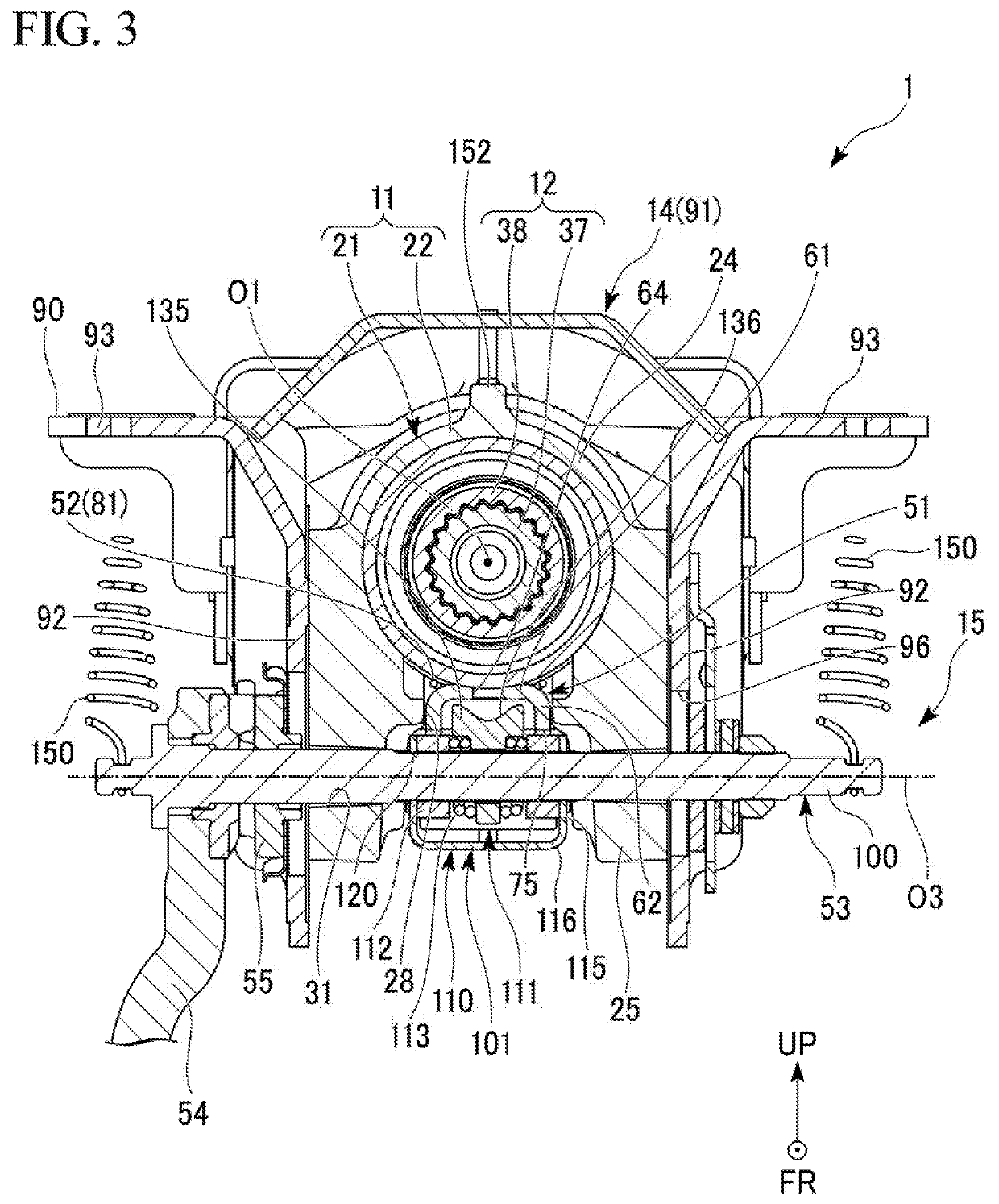
[0020]According to the aspect, at the time of the telescopic motion, the telescopic stopper and the telescopic restricting portion abut onto each other in a direction intersecting the front-rear direction such that a load that acts between the telescopic stopper and the telescopic restricting portion in a normal direction of a contact surface between the telescopic stopper and the telescopic restricting portion is decomposed into a load in a forward direction and a load in a vertical direction. That is, a component of the load that acts between telescopic stopper and the telescopic restricting portion at the time of the telescopic motion can be caused to act in a direction that is different from a direction in which the telescopic stopper is rotated such that the locked state is entered (forward direction). Therefore, it is possible to reliably restrict the inner column from moving forward with respect to the outer column while suppressing unexpected rotation of the telescopic stopper.
[0021]According to the aspects, it is possible to suppress a variation in load at the time of a collapse stroke and to achieve a stable impact absorption load.

Problems solved by technology

Therefore, the variation in load at the time of the collapse stroke is great.

Method used


Image

  • Steering device
  • Steering device
  • Steering device

Examples


Embodiment Construction

[0043]Next, an embodiment of the present invention will be described on the basis of drawings.

[0044]

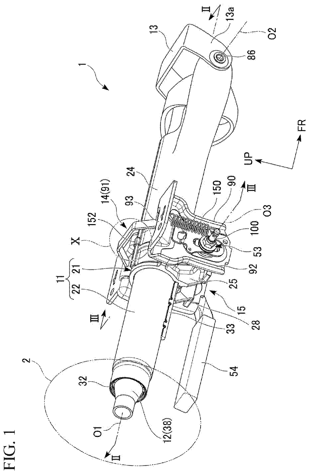
[0045]FIG. 1 is a perspective view of a steering device 1.

[0046]As shown in FIG. 1, the steering device 1 is installed in a vehicle. The steering device 1 adjusts the steering angle of vehicle wheels in accordance with a rotation operation of a steering wheel 2.

[0047]The steering device 1 is provided with a column unit 11, a steering shaft 12, a fixation bracket (front bracket 13 and rear bracket 14), and a switching unit 15. Each of the column unit 11 and the steering shaft 12 is formed along an axis O1. Therefore, in the following description, a direction in which the axes O1 of the column unit 11 and the steering shaft 12 extend will be simply referred to as an shaft axial direction, a direction orthogonal to the axes O1 will be referred to as a shaft radial direction, and a direction around the axes O1 will be referred to as a shaft circumferential direction in some cases.

[0048]Th...


PUM


Abstract

A steering device is configured such that an EA stopper and a telescopic lock tooth are engaged with each other such that an inner column and a fixation member move forward with respect to a hanger bracket in a case where a load in a forward direction that acts on the inner column is equal to or greater than a predetermined value. Regarding a telescopic stopper, the fixation member comes into contact with the telescopic stopper in accordance with movement of the inner column and the fixation member with respect to the hanger bracket such that the telescopic stopper rotates in a withdrawal direction in which the telescopic stopper is withdrawn from the fixation member.

Description

CROSS-REFERENCE TO RELATED APPLICATION[0001]Priority is claimed on Japanese Patent Application No. 2017-221854, filed on Nov. 17, 2017, the contents of which are incorporated herein by reference.BACKGROUND OF THE INVENTIONField of the Invention[0002]The present invention relates to a steering device.Description of Related Art[0003]There is a steering device that has a telescopic function. The telescopic function is a function of adjusting the position of a steering wheel in a front-rear direction according to the physique or driving posture of a driver. Such a steering device is provided with an outer column and an inner column. The inner column is inserted into the outer column such that the inner column can be moved with respect to the outer column. The inner column rotatably supports a steering shaft to which the steering wheel is attached.[0004]In the above-described steering device, a configuration for alleviating an impact load, which is applied to a driver during a process in...

Claims


Application Information

Patent Timeline
Patent Type & Authority Patents(United States)
IPC IPC(8): B62D1/19B62D1/189B62D1/184
CPCB62D1/192B62D1/189B62D1/184
Inventor SHIROISHI, YOSHINORI
Owner YAMADA MANUFACTURING CO LTD
Learn More