Liquid Ejecting Apparatus and Method of Controlling the Same

a liquid ejecting and liquid ejecting technology, which is applied in the direction of printing, other printing apparatus, etc., can solve the problems of unstable ejection of ink droplets from the nozzle, risk of contamination of recording media and internal structure of the printer with ink, and defective ejection of ink droplets, so as to avoid the problem of instability of ejection

Active Publication Date: 2010-07-22
BROTHER KOGYO KK
View PDF10 Cites 0 Cited by
  • Summary
  • Abstract
  • Description
  • Claims
  • Application Information

AI Technical Summary

Benefits of technology

[0009]The present invention was made in view of the background art described above. It is therefore a first object of the present invention to provide a method of controlling a liquid ejecting apparatus, which alleviates the

Problems solved by technology

The destruction of the meniscus at the nozzles would result in leakage of the ink from the nozzles, and adhesion of the ink to an ejection surface of the head in which the nozzles are open, giving rise to a risk of contamination of a recording medium and an internal structure of the printer with the ink.
Further, the destruction of the meniscus would cause the foreign matte

Method used


Image

  • Liquid Ejecting Apparatus and Method of Controlling the Same
  • Liquid Ejecting Apparatus and Method of Controlling the Same
  • Liquid Ejecting Apparatus and Method of Controlling the Same

Examples


Embodiment Construction

[0031]One preferred embodiment of the present invention will be described by reference to the drawings.

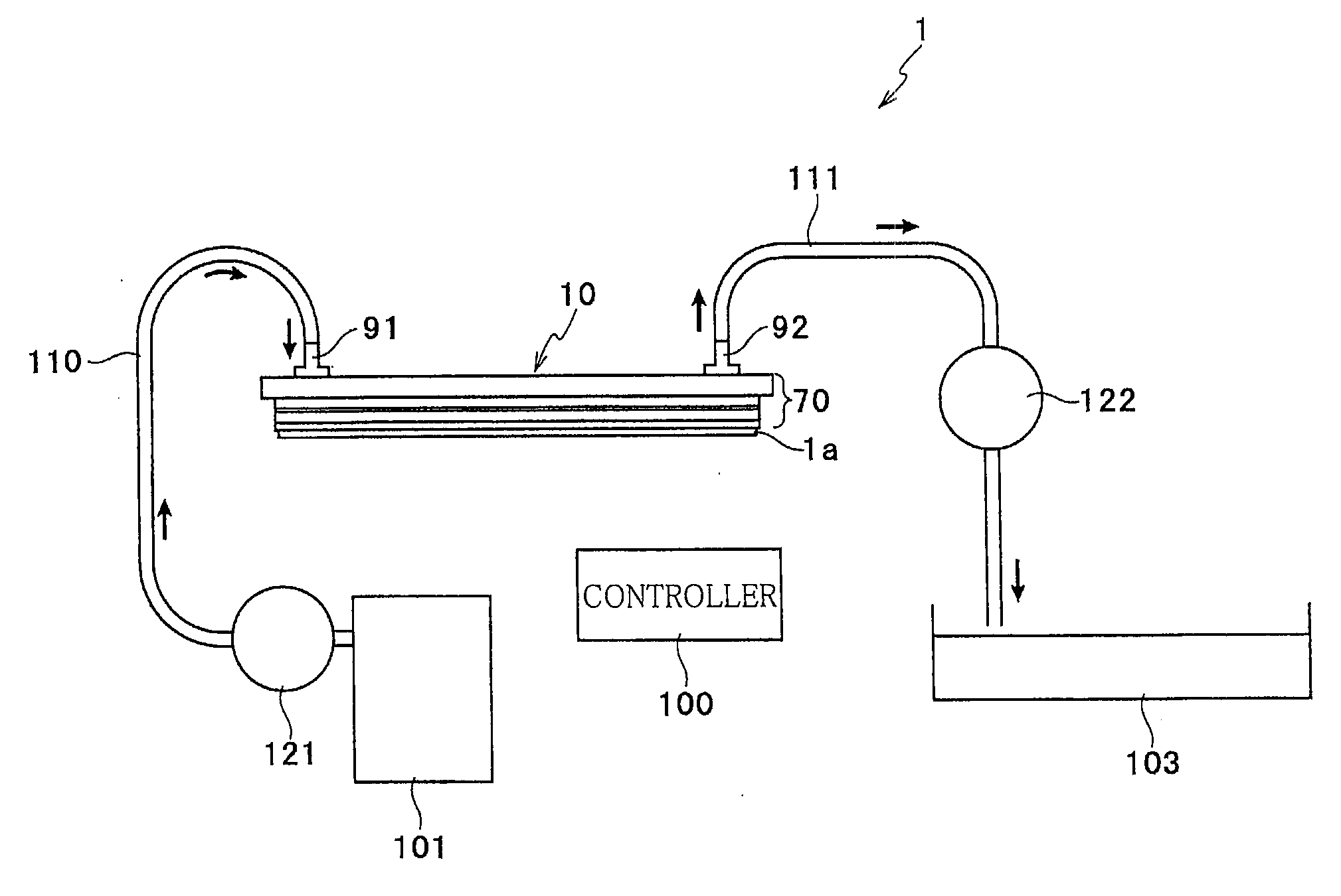
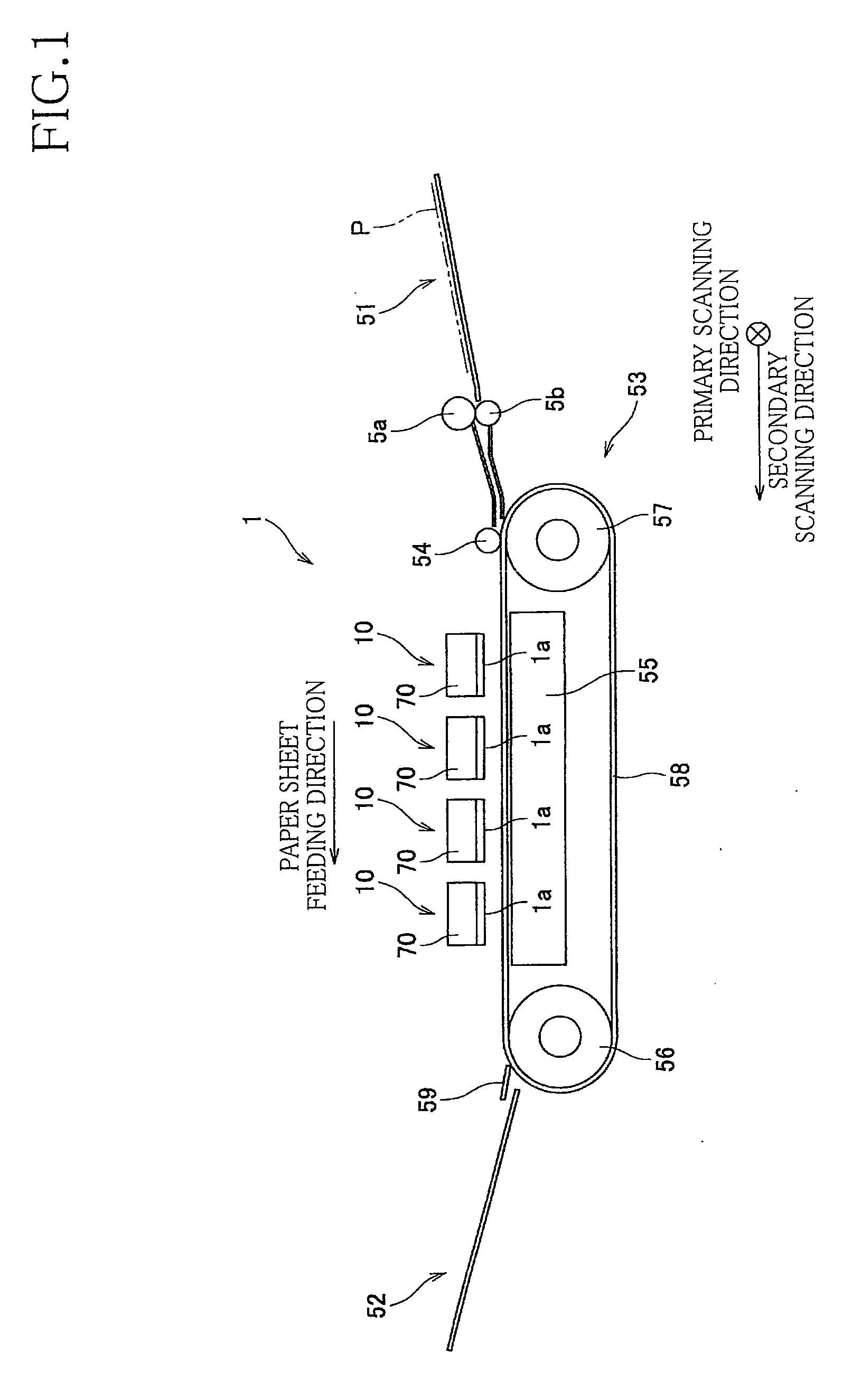
[0032]Referring first to the elevational view of FIG. 1, there is schematically shown a liquid ejecting apparatus in the form of an ink-jet printer 1 constructed according to the embodiment of this invention.

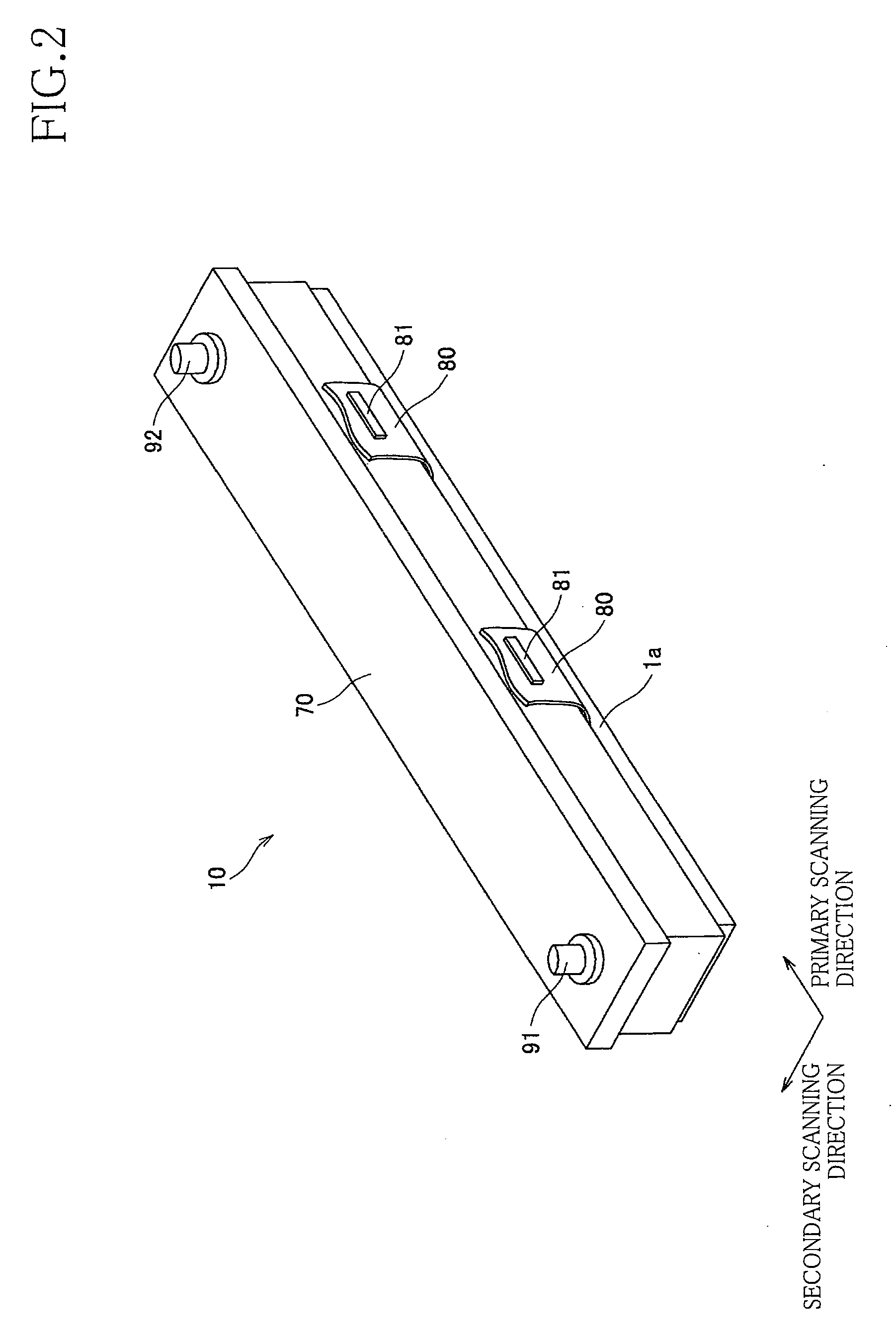
[0033]The ink-jet printer 1 is a color ink-jet line printer having four ink-jet heads 10 fixed to a main body thereof, as shown in FIG. 1. The four ink-jet heads 10 are provided to eject respective four different colors of ink, that is, magenta, yellow, cyan and black inks. The ink-jet printer 1 has a sheet feeding path extending from a sheet supply portion 51 located on its right side as seen in FIG. 1, to a sheet discharge portion 51 located on its left side as seen in FIG. 1. A sheet of paper P is fed by a pair of nip rollers 5a, 5b from the sheet supply portion 51 into a sheet feeding unit 53 while the paper sheet P is nipped by the nip rollers 5a, 5b.

[0034]The sheet feedi...


PUM


Abstract

A method of controlling a liquid ejecting apparatus including a liquid ejecting head having a supply portion, an ejecting portion, a discharge portion, and a filter portion dividing an internal passage within the head into an upstream passage communicating with the supply and discharge portions and a downstream passage communicating with the ejecting portion, and further including pumps respectively connected to the supply and discharge portions, and a control portion configured to control the pumps so as to satisfy P1R4+P2R3<P3(R3+R4), and P1−P2>Q1(R3+R4), during a maintenance operation to discharge a supplied liquid from the discharge portion through the upstream passage, wherein P1: and P2 are pressures at the respective supply and discharge portions during the maintenance operation, P3 is a meniscus-withstanding pressure at the filter portion, R3 is a liquid flow resistance in a passage from the supply portion to the filter portion, R4 is a liquid flow resistance in a passage from the filter portion to the discharge portion, and Q1 is a minimum amount of liquid supplied through the supply portion and discharged through the discharge portion, which minimum amount is required to discharge foreign matters existing in the upstream passage during the maintenance operation.

Description

CROSS REFERENCE TO RELATED APPLICATION[0001]The present application claims the priority from Japanese Patent Application No. 2008-217189 filed Aug. 26, 2008, the disclosure of which is herein incorporated by reference in its entirety.BACKGROUND OF THE INVENTION[0002]1. Field of the Invention[0003]The present invention relates to a liquid ejecting apparatus, and a method of controlling the liquid ejecting apparatus during maintenance thereof.[0004]2. Description of Related Art[0005]An ink-jet printer is known as an example of a liquid ejecting apparatus. The ink-jet printer has an ink-jet head having a multiplicity of nozzles for ejecting droplets of an ink, a supply port for receiving the ink supplied from an ink supply source such as an ink reservoir, and an internal passage system connecting the input port to the nozzles.[0006]Such a printer is arranged to perform a maintenance operation such as a purging operation, for maintaining a good condition of ejection of the ink droplets ...

Claims


Application Information

Patent Timeline
IPC IPC(8): B41J29/38
CPCB41J2/1707
Inventor HIROTA, ATSUSHI
Owner BROTHER KOGYO KK
Why Eureka
Try Eureka