
Inhaler

a technology of inhaler and insert, which is applied in the field of insert for inhaler, can solve the problems of long-term use or re-use of inhaler, large and complex construction, and high manufacturing cost, and achieve the effect of long and reliable service and economical use of materials

Active Publication Date: 2020-08-25
BOEHRINGER LNGELHEIM VETMEDICA GMBH
View PDF20 Cites 0 Cited by
  • Summary
  • Abstract
  • Description
  • Claims
  • Application Information

AI Technical Summary

Benefits of technology

The invention provides an insert and an inhaler that can be used on large animals, such as horses, for a long time without breaking down or becoming ineffective. This means that the materials used in the invention are economical and reliable, and can be used on larger animals without causing any additional expenses.

Problems solved by technology

In conjunction with their use in large animals, such as horses, inhalers have the disadvantage of requiring a very robust, relatively large and complex construction, which is expensive to manufacture.
At the same time, their use in large animals, unless the animals are physically restrained, rapidly leads to soiling by secretions or the like, which prevent longer-term use or re-use of the inhaler.

Method used


Image

  • Inhaler
  • Inhaler
  • Inhaler

Examples


second embodiment

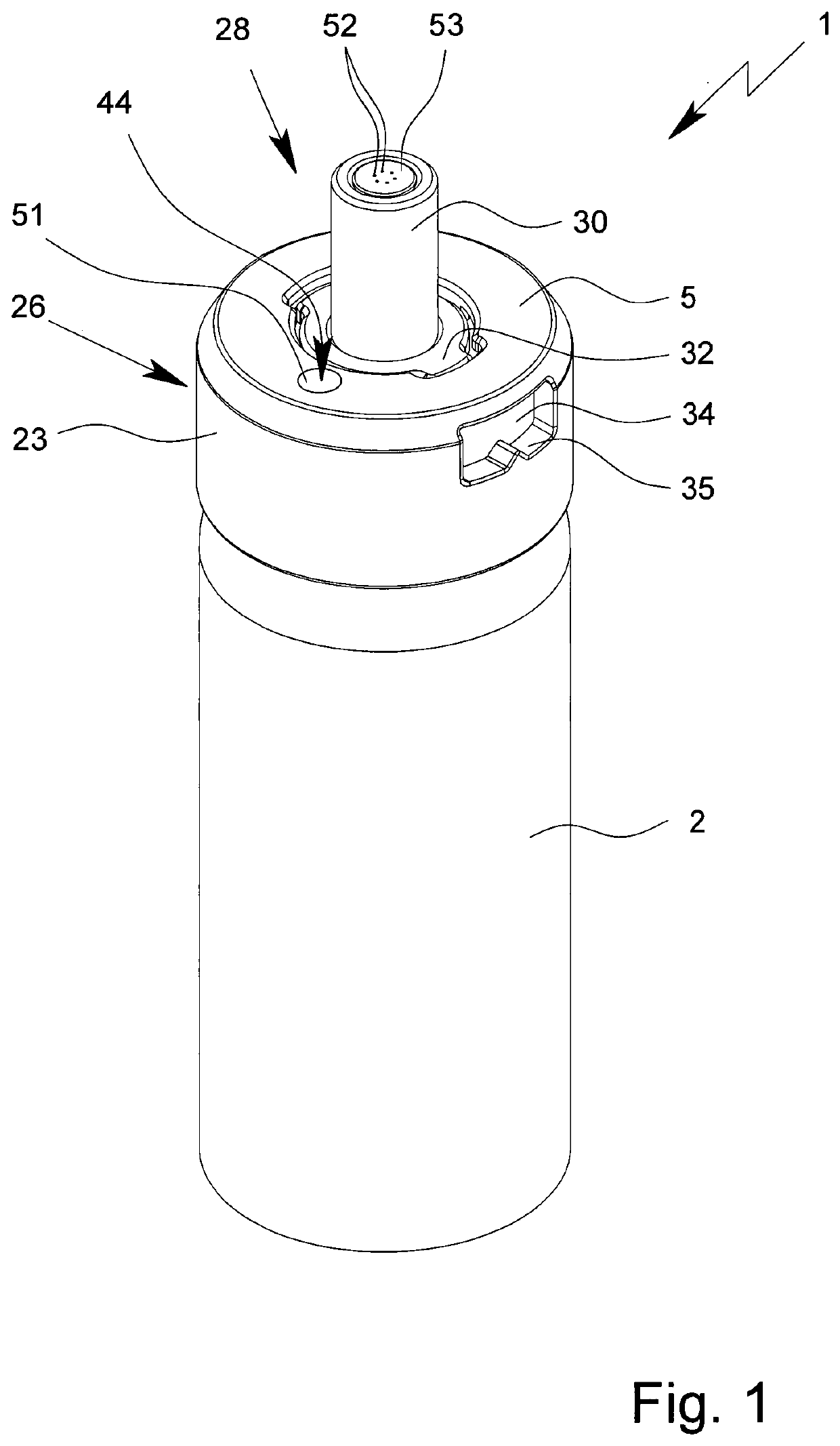
[0272]FIG. 13 shows a discharge nozzle 28 with an at least substantially star-shaped or snow flake-shaped nozzle element 53 which comprises the discharge openings 52 and / or forms a nozzle insert.

[0273]The nozzle element 53 may functionally correspond at least substantially to the novel element 53 according to FIGS. 12 and 12a and for this reason reference is particularly made to the option of an inclined direction of discharge A in describing them.

[0274]The nozzle element 53 from the embodiment shown in FIGS. 13 and 14 comprises five arm-shaped sections, each having discharge openings 52 in or on their ends. However, it is also possible to have more or fewer arm-shaped sections, for example, four or six. Optionally, a further discharge opening 52 may additionally be provided in a central region of the nozzle element 53 on which the arm-like sections are arranged.

[0275]FIG. 14 shows a perspective section through the discharge nozzle 28 from FIG. 13. The channel 31 may be connected t...

third embodiment

[0282]FIG. 15 shows, in a third embodiment, a proposed discharge nozzle 28 with five discharge openings 52. However, it is also possible to have a different number of discharge openings 52.

[0283]FIG. 16 shows a side view of the discharge nozzle 28 according to FIG. 15. FIG. 17 shows, in a section on the line XVII-XVII from FIG. 16, the supply means 59 which in the present instance is of at least substantially star-shaped configuration.

[0284]A star-shaped supply 59 with additional fluid connections between adjacent discharge openings 52 represents a good compromise between the contact surface for the pressure and a homogenous distribution of pressure between the discharge openings 52 and a uniform discharge quantity through the respective discharge openings 52.

[0285]Adjacent discharge openings 52 may be connected to one another by connecting channels 63, preferably at the ends or on a side facing to the channel 31 or the respective discharge openings 52. In particular, ends of the su...

fourth embodiment

[0296]FIG. 23 shows, in perspective view, the proposed discharge nozzle 28. FIG. 24 shows a side view of the discharge nozzle 28 according to FIG. 23. FIG. 25 shows a section through the discharge nozzle 28 of FIG. 23 taken along the section line XXIV-XXIV in FIG. 24 and FIG. 26 shows a section through the discharge nozzle 28 from FIG. 23 taken along the section line XXVI-XXVI in FIG. 24.

[0297]The discharge nozzle 28 from FIG. 23 comprises a plate-like nozzle element 53 with discharge openings 52. The nozzle element 53 is fixed to the nozzle body 30 by a lock nut 64. The lock nut 64 preferably has an internal thread which may correspond to an external thread on the nozzle body 30. The lock nut may alternatively or additionally also be latched on or otherwise secured or may be replaced by a nozzle element from the third embodiment.

[0298]The lock nut 64 may comprise mounting elements 65, particularly recesses for a tool.

[0299]The nozzle element 53 may be tightened directly against the...


PUM


Abstract

An insert which can be inserted into an inhaler, particularly for a horse has a reservoir for a medicament preparation held under excess pressure and a valve. The insert also has a nebulizer that is held directly on the reservoir and a discharge nozzle, associated with the nebulizer and fluidically connected to the valve, for forming an aerosol with the medicament preparation.

Description

BACKGROUND OF THE INVENTIONField of the Invention[0001]The present invention relates to an insert for an inhaler as well as an inhaler. In particular, the present invention relates to inhalers for horses or other large animals, with an adapter for a nostril or other respiratory orifice.Description of Related Art[0002]The invention further relates to inhalers which, on each actuation, dispense a defined dose or amount of a medicinal fluid held under excess pressure, for which reason these inhalers are also known as “pressurized metered-dose inhalers” (pMDI).[0003]A pMDI has a reservoir, which is filled with a medicament preparation and is kept under pressure by means of a propellant gas. The reservoir further comprises a metering valve for dispensing the medicament fluid. The metering valve is able to dispense a specified or measured amount of the medicament fluid each time the valve is activated. The fluid is dispensed by the movement of a valve element of the metering valve.[0004]U...

Claims


Application Information

Patent Timeline
Patent Type & Authority Patents(United States)
IPC IPC(8): A61M15/00A61D7/04
CPCA61M15/009A61D7/04A61M15/0086A61M15/0073A61M2250/00A61M15/08B65D83/206B65D83/22B65D83/30B65D83/384A61M2210/0618B05B11/108
Inventor RAHMEL, MARCUS RAINERJUNG, ANDREEWACHTEL, HERBERT
Owner BOEHRINGER LNGELHEIM VETMEDICA GMBH
Learn More