Method and apparatus for forming a multiple focus stack image

a stack image and stack image technology, applied in the field of multiple focus stack image formation, can solve the problems of time-consuming, time-consuming, and the need to maintain the focus over the whole length of the scan,

Active Publication Date: 2005-12-29
FFEI LTD
View PDF25 Cites 62 Cited by
  • Summary
  • Abstract
  • Description
  • Claims
  • Application Information

AI Technical Summary

Benefits of technology

[0023] For colour images, the sub-arrays preferably each comprise filters so as to receive light corresponding to particular colours. The focus device may effect the focus by movement of the array, or the target, or when the device comprises an imaging lens then by movement of the imaging lens or component parts of the imaging lens. When the focus device comprises fold mirrors, the focus device effects the focus by movement of the fold mirrors. A window of controllable optical thickness can also be used for this purpose, this being an electro-optical active quartz window for example or a rotatable window with a variable optical thickness as a function of the rotation angle.
[0024] The apparatus and method can be used in a number of imaging applications although it finds particular advantage in microscopy where the field of view and depth of field are typically rather limited.

Problems solved by technology

As mentioned in U.S. Pat. No. 6,711,283 one problem with this long strip scanning is that the focus must be maintained over the whole length of the scan.
A typical microscope slide is not manufactured to hold this sort of tolerance and when mounted may flex due to the mounting method or under the force of gravity in excess of one micron.
Unfortunately this is time consuming in building the focus map for each sample.
The problem with this method is that with small depth of focus in relation to the range of focus change in the sample, many layers of image will be needed to cover the full focus range and this will be time consuming.

Method used


Image

  • Method and apparatus for forming a multiple focus stack image
  • Method and apparatus for forming a multiple focus stack image
  • Method and apparatus for forming a multiple focus stack image

Examples


Embodiment Construction

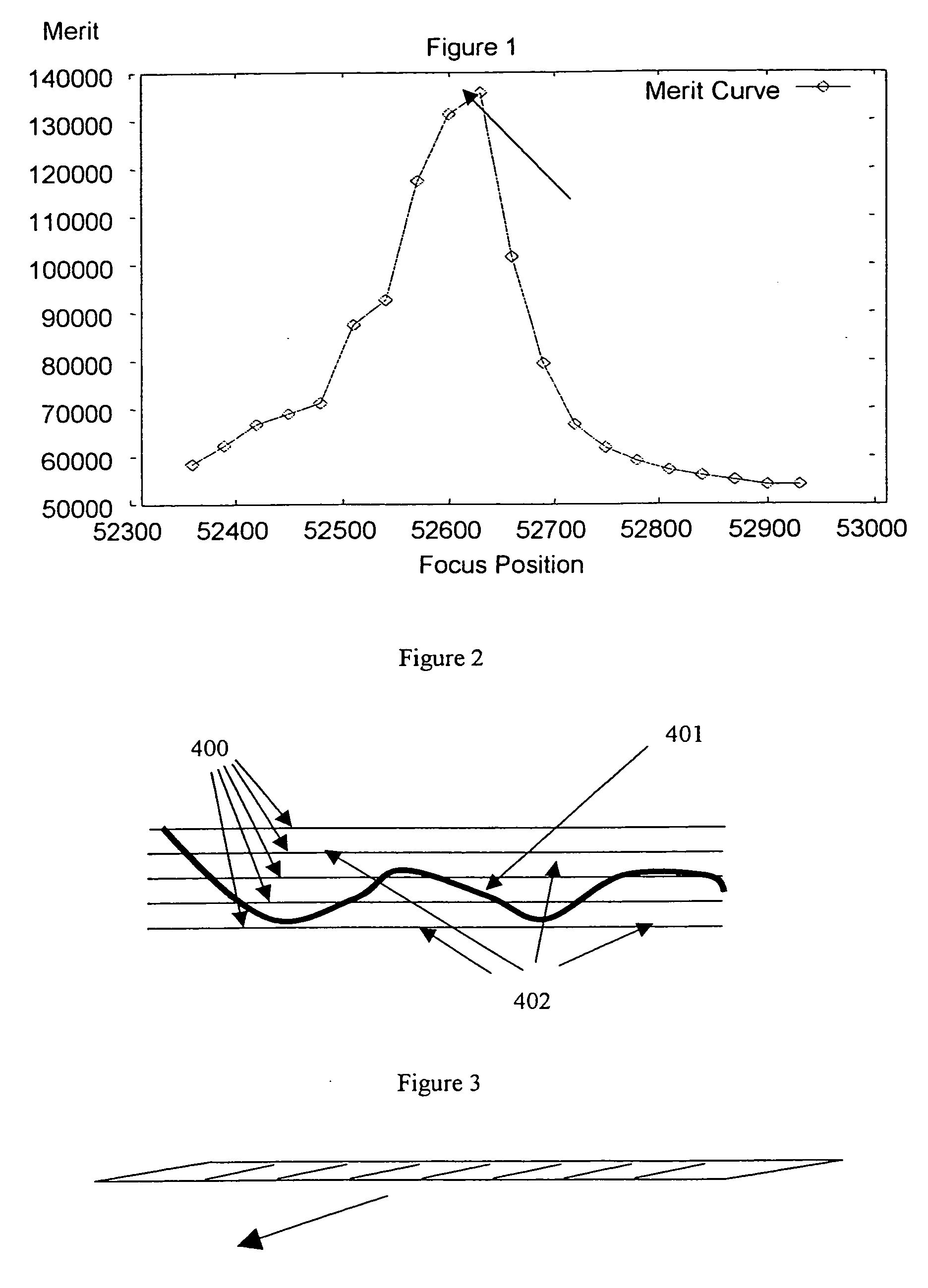
[0072] Normal line scanning involves a single line array of x pixels, each pixel typically corresponding to a detector in the array. For colour, a single line for each of the three colours is provided (RGB for example). This single line is then traversed in a direction perpendicular to the line of the detector array. The traverse speed is set so that after one “line time” of the detector, the detector has traversed by a distance of one pixel in the scan direction so that the next line time produces a line of pixels abutted to the previous line. This is shown in FIG. 3 where a 1D array is scanned in the direction indicated by the arrow.

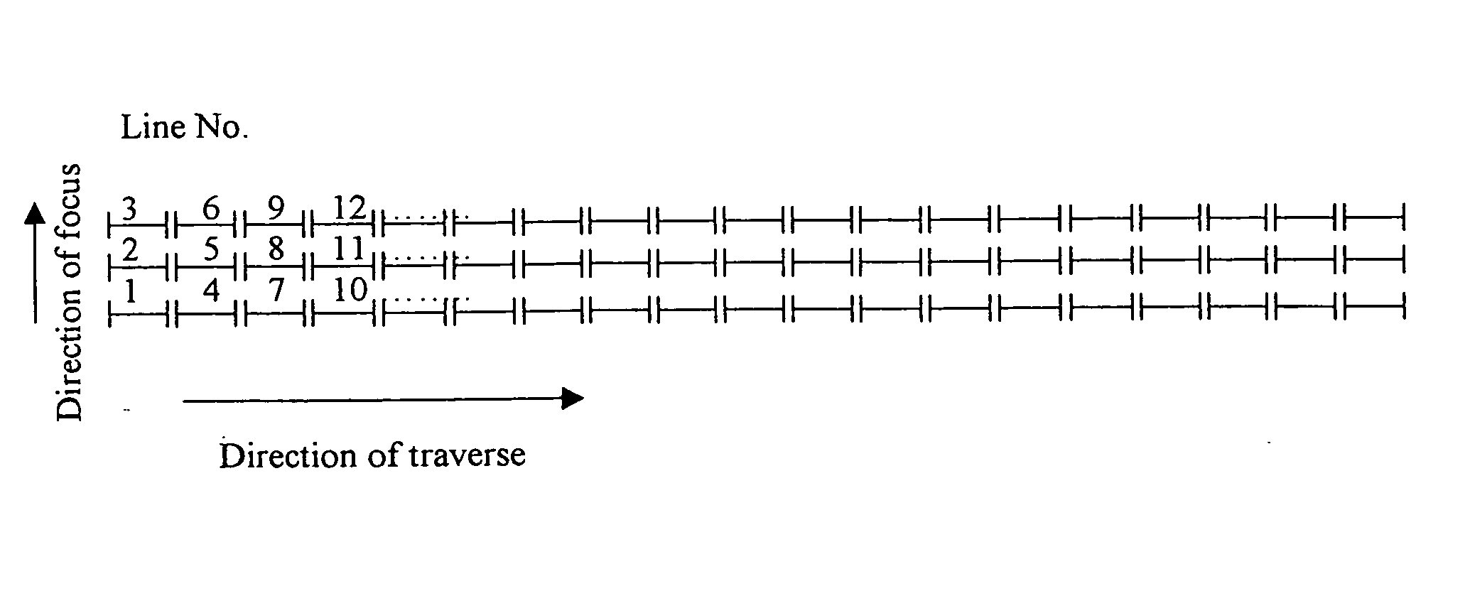
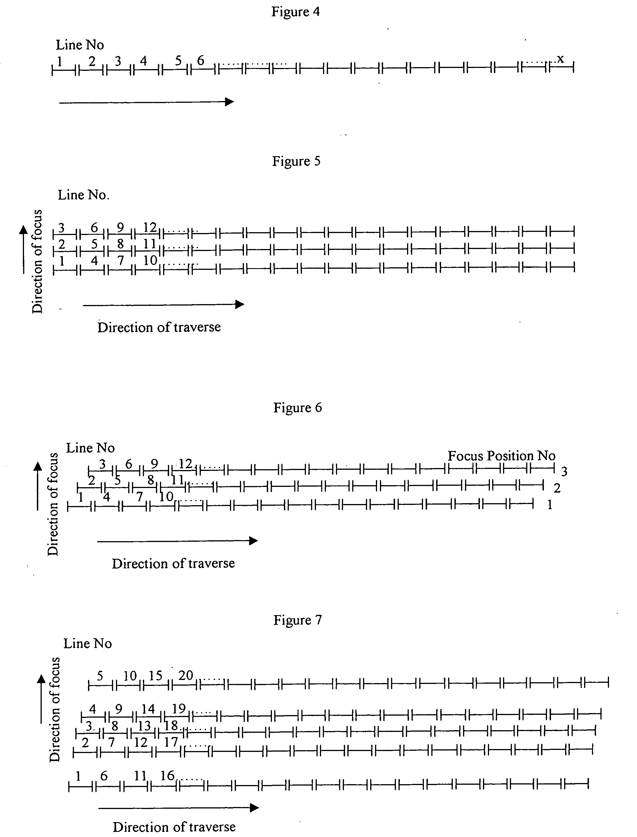
[0073]FIG. 4 is a representational layout of 1D array scanning as viewed from the end of the 1D array. The direction of the traverse is indicated by the arrow, with the first scan line being labelled “1”, the second “2” and so on. The simplest embodiment is to scan and to adjust the focus to different focus stack positions in between movements to the ...


PUM


Abstract

A method is provided of producing a multiple focus stack image of a target. The stack image has a plurality of images of the target, each image having a corresponding focal range or position. The method utilises relative scanning movement between the target and an array of light detectors, the array being used to repeatedly receive image information as scan lines from the target during the scan. During the scan the relative focus between the target and the array is modified between the focal range or position of the respective images so as to obtain the images in the stack. Each image is thereby formed from the image information obtained at the respective focal range or position during the scan. Apparatus for performing the method is likewise provided.

Description

[0001] The present invention relates to a method and apparatus for forming a multiple focus stack image. BACKGROUND TO THE INVENTION [0002] In a number of market sectors such as medical applications samples are examined with a microscope and digital images are generated with a 2D digital camera attached to the microscope. This has a restriction of limited area of the sample viewed being captured with the digital camera. For a 40× objective a typical area is only 0.7 mm wide. Given that the active area on a microscope slide is 64×24 mm this is only a very small area of the possible sample area. One answer to this is to step and repeat otherwise known as macro dither over the whole of the sample area. A more preferred process is to use a line scan device similar to that described in U.S. Pat. No. 6,711,283 where long strips of data can be collected of 0.7 by 64 mm. Then adjacent strips can be scanned and the images butted together or stitched together as described in patent GB2206011....

Claims


Application Information

Patent Timeline
Patent Type & Authority Applications(United States)
IPC IPC(8): G02B21/00G02B21/24G02B26/10
CPCG02B21/241
Inventor GOUCH, MARTIN PHILIP
Owner FFEI LTD
Why Eureka
Try Eureka