
Electrical power conversion system, control method and bridge rectifier

a power conversion system and bridge rectifier technology, applied in power conversion systems, ac-dc conversion, electrical equipment, etc., can solve the problems of relatively complex circuit structure, relatively high energy loss in circuit switching, and relatively complicated circuit construction of conventional current bridge rectifier circuits

Active Publication Date: 2020-08-25
ALPHA & OMEGA SEMICON CAYMAN
View PDF11 Cites 3 Cited by
  • Summary
  • Abstract
  • Description
  • Claims
  • Application Information

AI Technical Summary

Benefits of technology

The patent is about an electrical power conversion system that uses a bridge switching circuit, a switch, and a control unit. The control method involves detecting a certain voltage and comparing it with two preset thresholds. The switch is then turned on or off based on the voltage levels, and charging of the system is stopped if certain conditions are met. The technical effect of this patent is to provide a more efficient and reliable control method for electrical power conversion systems.

Problems solved by technology

However, a conventional current bridge rectifier circuit has a relatively complicated construction, and the energy loss in circuit switching is relatively high.
In one example, a type of bridge rectifier, disclosed in U.S. Pat. No. 9,843,251, requires applying bridge circuit's external signal to drive the bridge switch's gate, with a relatively complicated circuit structure and higher construction cost.
In another example, a type of bridge rectifier, disclosed in U.S. Pat. No. 8,804,389, requires applying an ultrahigh voltage (UHV) process for controller and needs extra high voltage level shift circuits thereby causing high circuit energy loss.
In other words, in the conventional solution, the bridge rectifier circuit usually performs extra switching operations within AC cycle, and the charging process is normally implemented within high voltage cycle, thereby increasing circuit energy loss and higher operation cost of the circuit.

Method used


Image

  • Electrical power conversion system, control method and bridge rectifier
  • Electrical power conversion system, control method and bridge rectifier
  • Electrical power conversion system, control method and bridge rectifier

Examples


Embodiment Construction

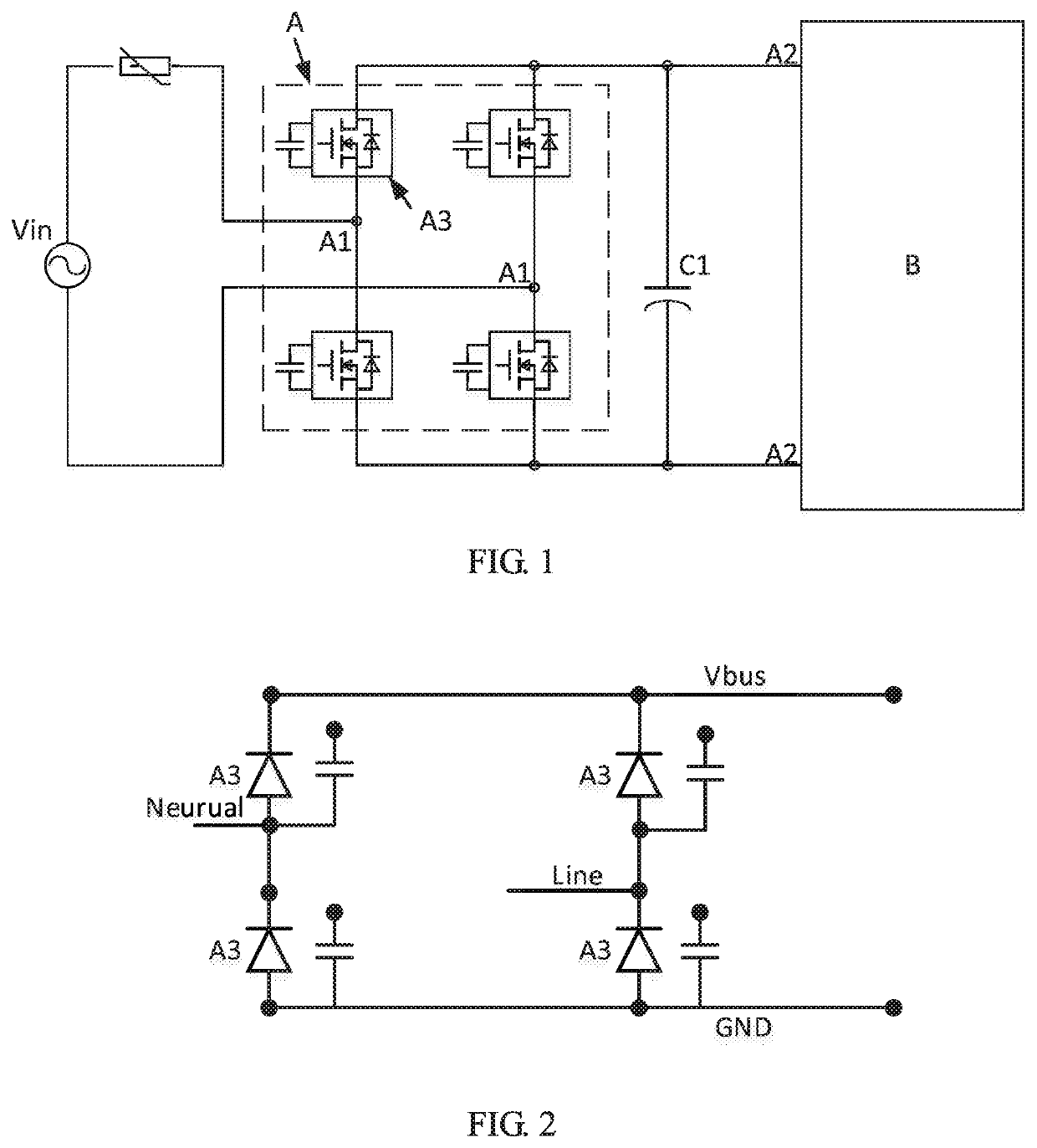
[0013]A technical solution of an electrical power conversion system is now provided to overcome the existing problems in the current technology. This electrical power conversion system is applicable to AC / DC power converter, specifically including one bridge switching circuit, where the input terminals of this circuit connected to the AC input terminals of the electrical power conversion system, and the output terminals of this circuit connected to the DC output terminals of the electrical power conversion system, respectively.

[0014]The bridge switching circuit includes several switching sub-circuits, each of them with its anode respectively connected to one of the AC input terminal and DC output terminal, and with its cathode respectively connected to another one of these two terminals.

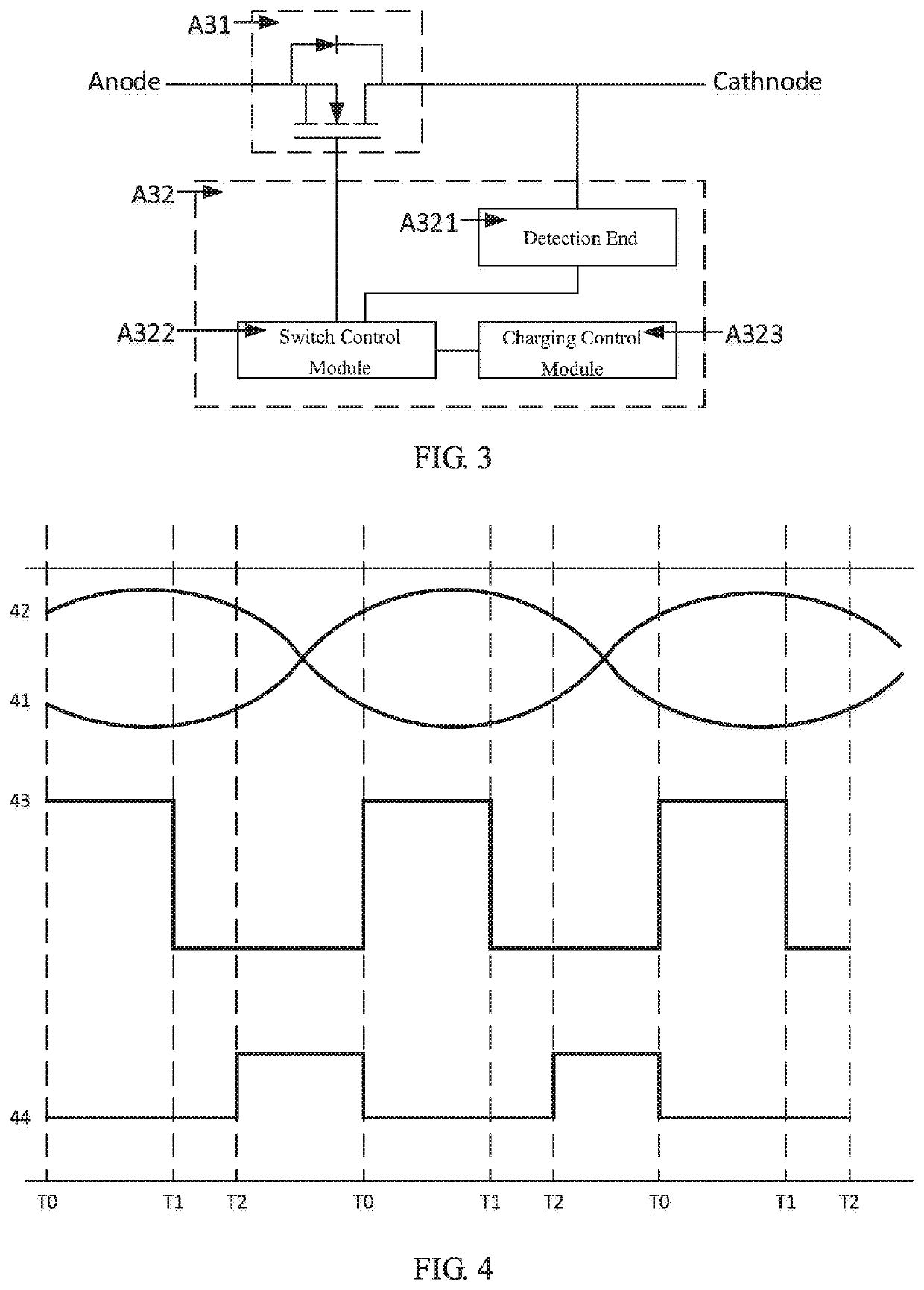
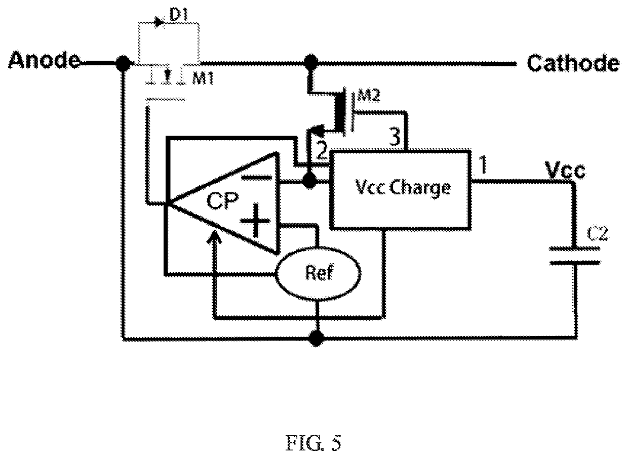
[0015]Each switching sub-circuit includes a switch and a control unit. The switch, connected between the anode and cathode of the switching sub-circuit, used to control on / off of the sub-circuit. The...


PUM


Abstract

A power conversion system includes a bridge switch circuit. The bridge switch circuit includes a plurality of switch sub-circuits, each switch sub-circuit includes: a switch for controlling switching of the switch sub-circuit; and a control unit configured to perform the following control cycle: When the voltage between the switch and the cathode is less than the first voltage threshold and the switch sub-circuit is not charged, the control unit controls the switch to be turned on, and starts charging the switch sub-circuit. When the voltage between the switch and the cathode is greater than a second voltage threshold, the control unit controls the switch to be turned off. When the charging voltage of the control unit is greater than the third voltage threshold, the control unit stops charging the switch sub-circuit. The circuit structure is simple and the circuit energy loss of the bridge rectifier is reduced.

Description

FIELD OF THE INVENTION[0001]This invention relates generally to circuit switching. More particularly, the present invention relates to an electrical power conversion system, a control method and a bridge rectifier.BACKGROUND OF THE INVENTION[0002]An AC / DC power converter is an electrical power conversion unit to convert alternating current (AC) into direct current (DC). In an AC / DC power converter, bridge rectifier circuit is often applied to act as the AC / DC power conversion system.[0003]However, a conventional current bridge rectifier circuit has a relatively complicated construction, and the energy loss in circuit switching is relatively high. In one example, a type of bridge rectifier, disclosed in U.S. Pat. No. 9,843,251, requires applying bridge circuit's external signal to drive the bridge switch's gate, with a relatively complicated circuit structure and higher construction cost. In another example, a type of bridge rectifier, disclosed in U.S. Pat. No. 8,804,389, requires a...

Claims


Application Information

Patent Timeline
Patent Type & Authority Patents(United States)
IPC IPC(8): H02M7/217H02M1/08H02M7/219H02M1/00
CPCH02M7/219H02M1/081H02M2001/007H02M1/08H02M1/007
Inventor CHEN, MING-HSUEH
Owner ALPHA & OMEGA SEMICON CAYMAN
Learn More