Display and Power Supply Control Method of a Display

a power supply and display technology, applied in the field of displays, can solve the problems of flicker or brightness variation of the display, high variance of the output voltage of the power supply, and the control method disclosed in u.s. patent no. 5,910,887 cannot be applied to the pfm control mod

Active Publication Date: 2013-03-14
AU OPTRONICS CORP
View PDF6 Cites 2 Cited by
  • Summary
  • Abstract
  • Description
  • Claims
  • Application Information

AI Technical Summary

Benefits of technology

[0010]Referring to one embodiment of the present invention, a display comprises a panel, a pixel driving unit, and a power supply. The panel comprises a plurality of pixels arranged in a matrix manner. The pixel driving unit drives the plurality of pixels, and the power supply electrically coupled to the pixel driving unit provides an output voltage to the pixel driving unit. Moreover, the power supply comprises an input power source, an output capacitor and a control unit. The output capacitor provides the output voltage to the pixel driving unit. The control unit controls the input power source to charge the output capacitor when not refreshing the pixels and to stop charging the output capacitor when refreshing the pixels in a frame period of the display.
[0011]Referring to another embodiment of the present invention, another display comprises a panel, a pixel driving unit, and a power supply. The panel comprises a plurality of pixels arranged in a matrix manner. The pixel driving unit drives the plurality of pixels, and the power supply electrically coupled to the pixel driving unit provides an output voltage to the pixel driving unit. Moreover, the power supply comprises an input power source, an output capacitor and a control unit. The output capacitor provides the output voltage to the pixel driving unit. The control unit controls the input power source to charge the output capacitor in a vertical blanking period of a frame period of the display and to stop charging the output capacitor in a plurality of horizontal blanking periods in the frame period of the display and when refreshing the pixels.
[0012]Referring to another embodiment of the present invention, a control method for controlling a power supply of a display which includes a plurality of pixels is disclosed. The power supply control method comprises providing the power supply comprising an output capacitor for supplying an output voltage to the display; in a frame period of the display, charging the output capacitor when not refreshing the pixels; and in the frame period of the display, stopping charging the output capacitor when refreshing the pixels.
[0013]Referring to another embodiment of the present invention, another control method for controlling a power supply of a display which includes a plurality of pixels is disclosed. The power supply control method comprises providing the power supply comprising an output capacitor for supplying an output voltage to the display; in a frame period of the display, charging the output capacitor in a vertical blanking period of the frame period of the display; and in the frame period of the display, stopping charging the output capacitor in a plurality of horizontal blanking periods of the display and when refreshing the pixels.

Problems solved by technology

However, U.S. Pat. No. 5,910,887 does not take into consideration whether restricting the switching time of the power supply would still effectively keep the output voltage of the power supply at a reference voltage or not.
In other words, restriction of the switching time of the power supply may lead to a high variance of the output voltage of the power supply, which would cause flicker or brightness variation of a display.
However, the control method disclosed in U.S. Pat. No. 5,910,887 cannot be applied to the PFM control mode.
However, a higher switching frequency of the DC / DC power supply would lead to higher power consumption.

Method used


Image

  • Display and Power Supply Control Method of a Display
  • Display and Power Supply Control Method of a Display
  • Display and Power Supply Control Method of a Display

Examples


first embodiment

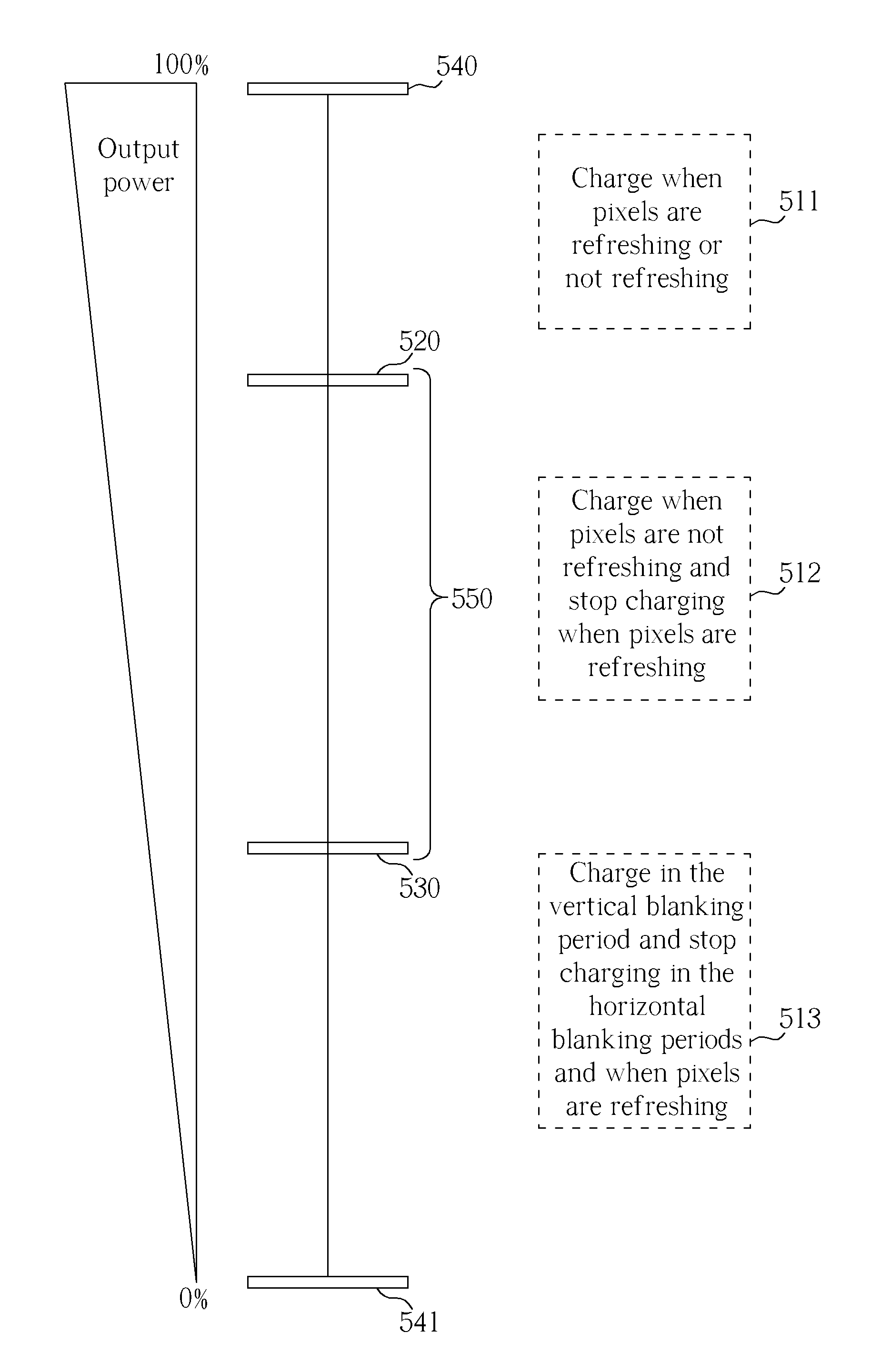
[0037]Please refer to FIG. 4 again. For the purpose of controlling the power supply 430 in cooperation with the driving of pixels 411 of panel 410, two embodiments are disclosed in this invention. In a first embodiment, the control unit 435 receives the vertical blanking signal and the horizontal blanking signal from the timing controller 440, which respectively indicate the vertical blanking period and the horizontal blanking period of the panel 410. As a result, the control unit 435 can control the input power source 432 to charge the output capacitor 437 during these two periods through indications of these two signals, respectively.

[0038]In the first embodiment, the timing controller 440 comprises a vertical synchronization signal input unit 4401 and a horizontal synchronization signal input unit 4402 for receiving the vertical synchronization signal and the horizontal synchronization signal, respectively. To coordinate control of the power supply 430 with refreshing of the pixe...

second embodiment

[0039]In the second embodiment, the control unit 435 receives the horizontal synchronization signal and / or the vertical synchronization signal from a video data source, and determines the vertical blanking period and the horizontal blanking period by counting a system clock with a counter. In this embodiment, the third input unit 4353 and the fourth input unit 4355 of the control unit 435 can respectively receive the vertical synchronization signal and the horizontal synchronization signal for coordinating control of the power supply 430 and refreshing of the pixels 411.

[0040]Please refer to FIG. 6 with FIG. 4. FIG. 6 shows operation waveforms of the display in the second mode. The waveforms in FIG. 6 include a horizontal synchronization signal 610, a vertical synchronization signal 620, a switch voltage (VDS) in PFM mode 630, a horizontal blanking signal 640, a vertical blanking signal 650, and a switch voltage (VDS) in PWM mode 660. According to the horizontal synchronization sign...


PUM


Abstract

A display includes a display panel, a pixel driving unit and a power supply for supplying power to the pixel driving unit. The display panel includes a plurality of pixels arranged in a matrix manner. The pixel driving unit is used for driving the pixels. The power supply includes an input power source, an output capacitor for providing an output voltage, and a control unit for controlling the input power source, such that in a frame period, the input power source charges the output capacitor during the non-refreshing duration of the pixels by the input power source and stops charging the output capacitor during the refreshing duration of the pixels.

Description

BACKGROUND OF THE INVENTION [0001]1. Field of the Invention[0002]The present invention relates to displays, and particularly to a power supply of a display.[0003]2. Description of the Prior Art[0004]Please refer to FIG. 1, which is a block diagram of a driving structure of a display 100. The display 100 includes an AC / DC converter 110, a pixel driving unit 120, a panel 130 having a plurality of pixels 131, a switching-type DC / DC converter 140, and a timing controller (Tcon) 150. The AC / DC converter 110 converts AC power to appropriate DC power, which is provided to the DC / DC converter 140. The DC / DC converter 140 converts the DC power provided by the AC / DC converter 110 to another DC power, which is provided to the pixel driving unit 120 for driving the pixels 131 arranged in a matrix. Moreover, the driving sequence of the plurality of pixels 131 is controlled by the timing controller 150, which generally includes two input units for receiving horizontal synchronization signal (Hsyn...

Claims


Application Information

Patent Timeline
Patent Type & Authority Applications(United States)
IPC IPC(8): G09G5/00
CPCG09G2330/06G06F1/3218G09G2310/08G06F1/3265Y02B60/1242Y02D10/00
Inventor HUANG, HUNG-MINKUO, SHIH-CHIEH
Owner AU OPTRONICS CORP
Why Eureka
Try Eureka