All-terrain vehicle and its seat installation structure

a technology for installing structures and seats, applied in the field of all-terrain vehicles, can solve the problems of affecting driving comfort, instability of the backrest assembly structure, and all-terrain vehicles, and achieve the effect of improving the stability of the seat installation structure of all-terrain vehicles

Active Publication Date: 2020-09-15
ZHEJIANG CFMOTO POWER CO LTD
View PDF15 Cites 1 Cited by
  • Summary
  • Abstract
  • Description
  • Claims
  • Application Information

AI Technical Summary

Benefits of technology

[0006]In view of this, the invention provides a type of seat installation structure of an all-terrain vehicle to improve the stability of seat installation structure. The invention also provides an all-terrain vehicle using such a seat installation structure.
[0021]The seat installation structure of an all-terrain vehicle provided by this invention includes the cab frame and the seat backrest arranged on the frame. The back mounting side of the seat backrest includes the first mounting part and the second mounting part arranged up and down respectively. The first mounting part includes the upper support frame located at the upper end of the frame. The installation hole is on the upper support frame, and the installation pin extends out of the seat backrest to be inserted into the installation hole. The second mounting part includes the lower support frame located at the lower end of the frame. The lower end of the seat backrest includes the installation buckle to be mounted on the lower support frame. The seat backrest is fixed inside the cab by mounting the first mounting part and second mounting part of the upper part and lower part of the seat backrest onto the frame. The seat backrest is supported by the upper support frame of the first mounting part. The installation pin extends out of the seat backrest and is inserted into the installation hole to limit the top of the seat backrest. The lower end of the seat backrest is supported by the second installation part. The second installation part includes the lower support frame at the lower end of the frame. The lower end of the seat backrest is provided with the installation buckle. The installation buckle is mounted on the lower support frame such that the lower end of the seat backrest is supported by the lower support frame. The installation structure of the seat backrest is supported by the bottom installation buckle. The top of the seat backrest is limited by the inserting of the installation pin into the installation hole to prevent the seat backrest from moving up and down on the frame and vibrating during vehicle travel, so the stability of the seat installation structure of the all-terrain vehicle is improved.

Problems solved by technology

However, existing backrest assembly technology leaves a large interstice between the backrest and the frame, resulting in instability of the backrest assembly structure and noise produced during vehicle travel, so driving comfort is affected.
Therefore, how to improve the stability of a seat installation structure of an all-terrain vehicle is a technical defect which urgently needs to be solved for those skilled in the art.

Method used


Image

  • All-terrain vehicle and its seat installation structure
  • All-terrain vehicle and its seat installation structure
  • All-terrain vehicle and its seat installation structure

Examples


Embodiment Construction

[0027]The invention is a type of seat installation structure of an all-terrain vehicle which improves the stability of the seat. The invention is also a type of all-terrain vehicle using the inventive seat installation structure.

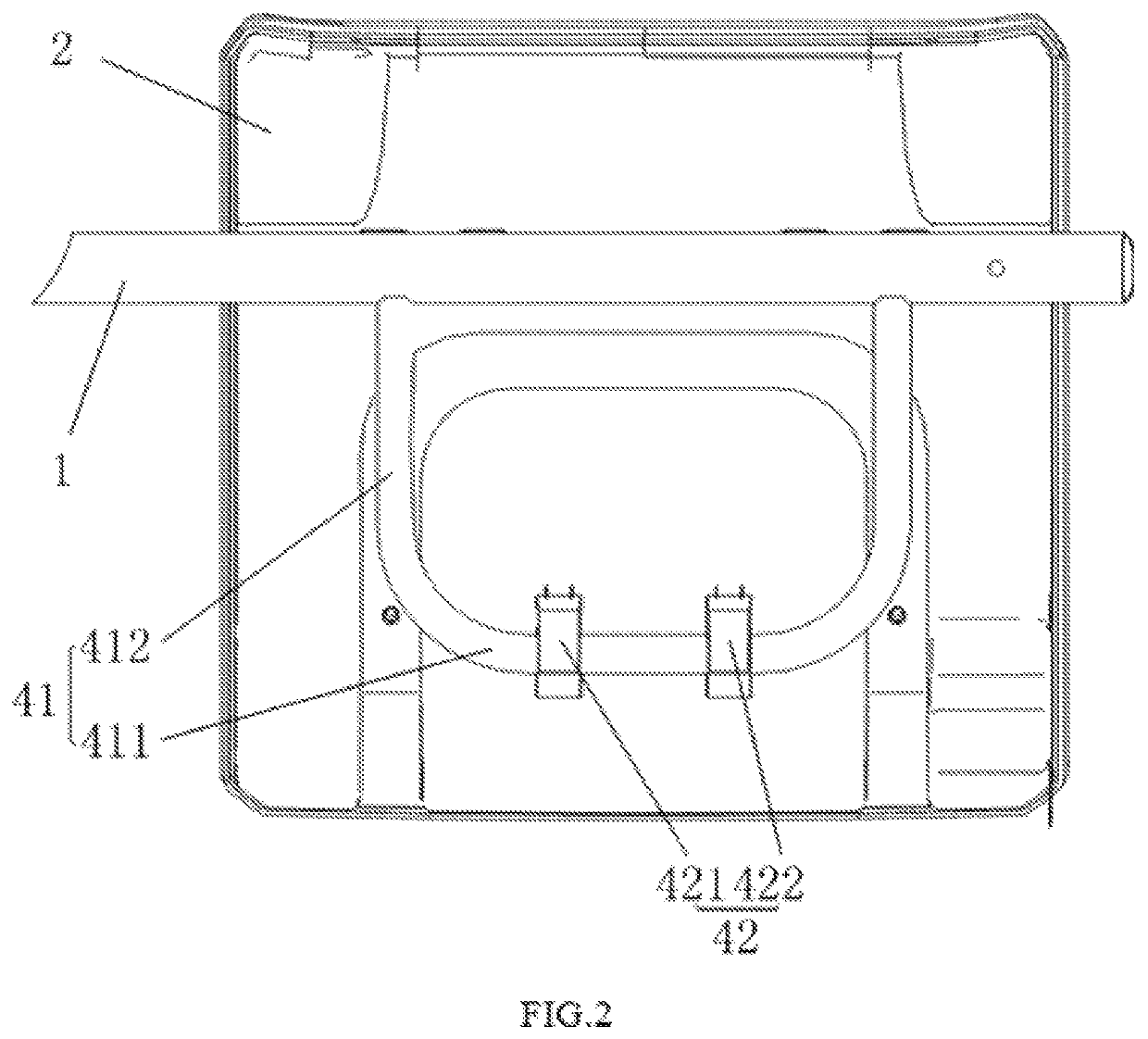
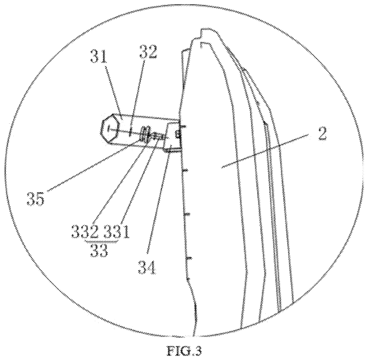
[0028]As shown in FIG. 1, a seat backrest 2 is arranged on a frame 1 which is part of the frame of an all-terrain vehicle. The back mounting side of the seat backrest 2 includes a first mounting part 3 and a second mounting part 4 arranged up and down respectively. The first mounting part 3 includes an upper support frame 31 (identified in FIG. 3) located at the upper end of the frame. An installation hole 32 is formed in the upper support frame 31. An installation pin 33 extends out of the seat backrest 2. As part of securing the seat backrest 2 to the frame 1, the installation pin 33 is inserted into the installation hole 32. The second mounting part 4 includes a lower support frame 41 (identified in FIG. 2) located at the lower end of the frame 1. An inst...


PUM


Abstract

The invention provides a type of all-terrain vehicle seat installation structure; it includes the cab frame and the seat backrest arranged on the frame; the back mounting side of the seat backrest includes the first mounting part and the second mounting part arranged up and down respectively. The first mounting part includes the upper support frame located at the upper end of the frame; the installation hole is arranged on the upper support frame; the installation pin inserted into the installation hole is extended out of the seat backrest. The second mounting part includes the lower support frame located at the lower end of the frame; the lower end of the seat backrest is provided with the installation buckle mounted on the lower support frame. The top of the seat backrest is limited by the installation pin being inserted into the installation hole; the seat backrest is supported by the bottom installation buckle; the top of the seat backrest is limited by the inserting installation structure of the installation pin and the installation hole to avoid the seat backrest moving up and down on the frame, so the stability of the seat installation structure of the all-terrain vehicle is improved. The invention also provides a type of all-terrain vehicle provided with the seat installation structure of the all-terrain vehicle as described above.

Description

CROSS-REFERENCE TO RELATED U.S. APPLICATION(S)[0001]None.FIELD OF THE INVENTION[0002]The invention relates to the technical field of the all-terrain vehicle, particularly to a type of all-terrain vehicle and its seat installation structure.BACKGROUND OF THE INVENTION[0003]All-terrain vehicles are commonly known as “beach vehicles”, or “all-terrain four-wheel off-road motor vehicles”. Such vehicles are simple and practical, can provide good off-road performance, and are generally not equipped with a canopy. As used herein, the term “all-terrain vehicle” means a vehicle that can travel on rugged terrain and can move freely on terrain over which ordinary vehicles find difficult to travel. Some people also call such a vehicle a “four-wheel motorcycle” because its structure is very similar to motorcycle and many parts are common to motorcycles. Such vehicles are used widely and are is not limited by road conditions.[0004]For one type of all-terrain vehicle with a cab, the seats are arran...

Claims


Application Information

Patent Timeline
Patent Type & Authority Patents(United States)
IPC IPC(8): B60N2/68B60N2/72B60N2/01B60N2/015B60N2/50B62D21/18B60N2/38
CPCB60N2/682B60N2/72B62D21/186B60N2/503B60N2/38B60N2/01583B60N2002/684B60N2/005
Inventor ZOU, PENGFEI
Owner ZHEJIANG CFMOTO POWER CO LTD
Why Eureka
Try Eureka