Supercharge Your Innovation With Domain-Expert AI Agents!

Vacuum nose roll

a technology of vacuum nose and roller, which is applied in the direction of shaft and bearing, rotary machine parts, bearings, etc., can solve the problems of component flipping, skewed, or even flying off the conveyer system, and the source of production errors or malfunctions

Active Publication Date: 2020-09-22
KIMBERLY-CLARK WORLDWIDE INC
View PDF48 Cites 0 Cited by
  • Summary
  • Abstract
  • Description
  • Claims
  • Application Information

AI Technical Summary

Benefits of technology

The patent text describes a vacuum chamber that is designed to have no obstructions. The technical effect of this design is that it allows for smoother operation and better performance of the vacuum chamber.

Problems solved by technology

The hand-off from one conveyer system to the next can be a source of production errors or malfunctions.
For instance, the materials and article components may become wrinkled, an edge of the materials or article components may be become folded over, or, particularly in high speed manufacturing processes, air may get under a leading edge of an article component, causing the component to flip, become skewed, or even fly off of the conveyer system.

Method used


Image

  • Vacuum nose roll
  • Vacuum nose roll
  • Vacuum nose roll

Examples


Embodiment Construction

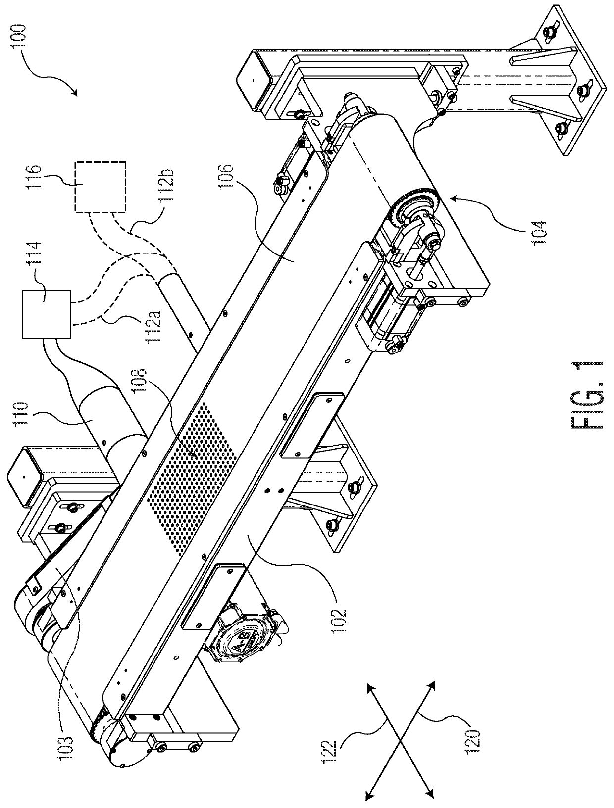
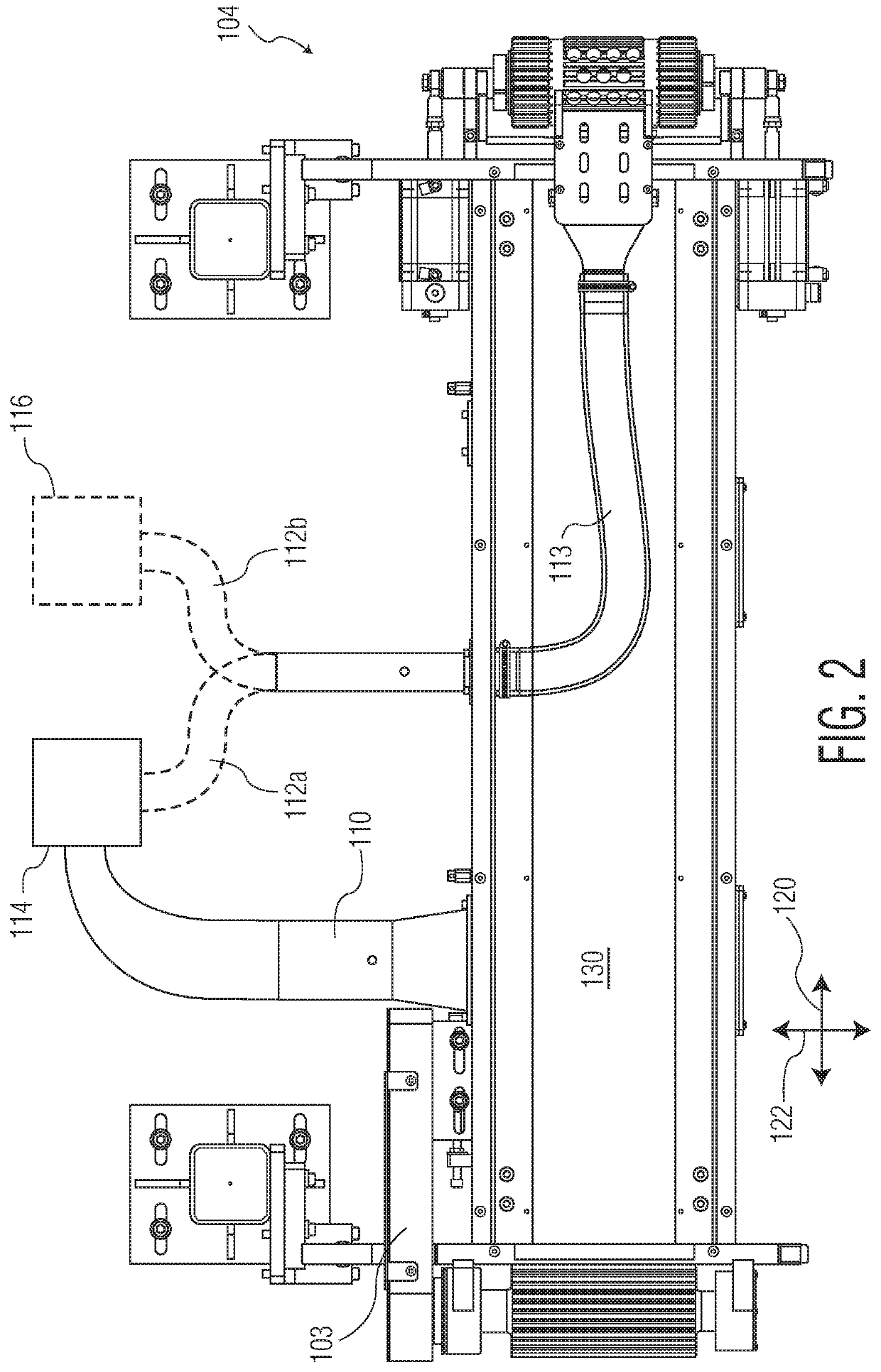
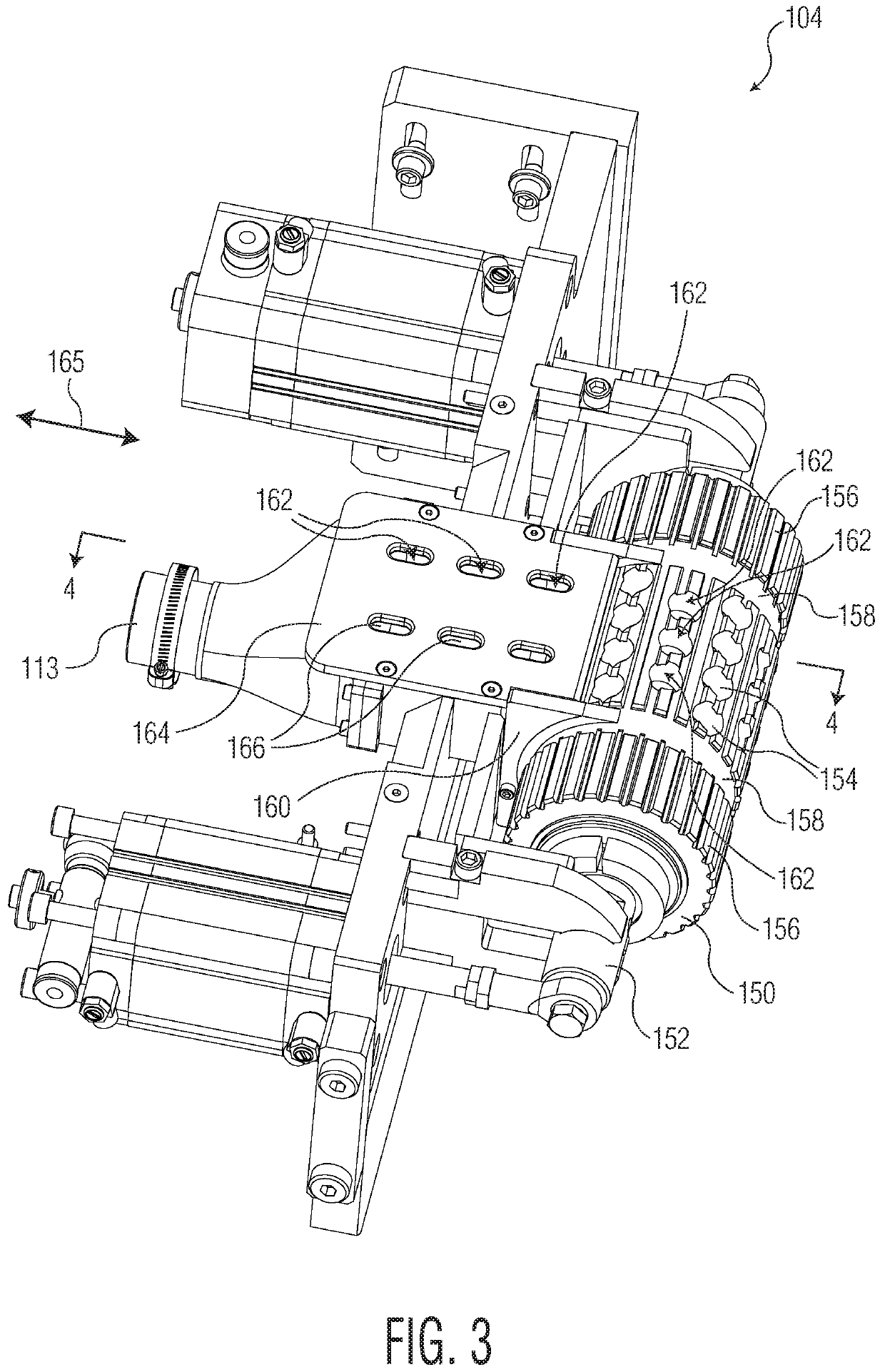
[0032]The present disclosure is generally directed towards several alternative designs and methods of for conveying material. In some high speed manufacturing processes, moving materials and article components from one conveyer system to another conveyer system can introduce undesired movement of the materials and article components, from slight skewing of the materials and components with respect to desired positions all the way to complete dislodgment of the materials and components from the conveyer system. Generally, conveyer systems employ vacuum pressure to help keep materials and article components in position on the conveyer as the materials and components move within the system. However, this vacuum pressure can be difficult to localize at front and / or rear ends of conveying systems, thereby making the transition from one conveying system to another conveying system a source of manufacturing problems. The present disclosure relates to vacuum conveying systems with improved ...


PUM


Abstract

Apparatus for transporting material in a manufacturing process are disclosed. A disclosed vacuum conveyer system may comprise a vacuum box extending between a first box end and a second box end, the vacuum box comprising a vacuum box vacuum chamber, a nose roll disposed adjacent to the first box end, the nose roll comprising a nose roll vacuum chamber, and a foraminous member disposed about both of the nose roll and the vacuum box. The vacuum system may further comprise a first airflow conduit connecting the vacuum box vacuum chamber to a vacuum source and a second airflow conduit connecting the nose roll vacuum chamber to the vacuum source.

Description

TECHNICAL FIELD[0001]The present disclosure is directed to apparatuses for conveying material.BACKGROUND OF THE DISCLOSURE[0002]One important process step in the manufacture of many items is the transporting of material along a manufacturing pathway. In the specific case of manufacturing absorbent articles in a continuous process, materials and article components that form part of the produced absorbent articles move along different conveyer systems in the manufacturing process. Processing steps such as bonding steps or application of absorbent material or the like may happen along the manufacturing process to produce the absorbent articles. In some instances, the materials and article components may be transferred between adjacent conveyer systems within the manufacturing process. The hand-off from one conveyer system to the next can be a source of production errors or malfunctions. For instance, the materials and article components may become wrinkled, an edge of the materials or ...

Claims


Application Information

Patent Timeline
Patent Type & Authority Patents(United States)
IPC IPC(8): B65G39/02B65G15/58F16C13/00
CPCB65G15/58B65G39/02F16C13/00F16C2300/62B65G2812/02217B65G2811/06B65G21/2036
Inventor KONETZKE, RICHARD M.VENTURINO, MICHAEL B.MATTIOLI, MICHAEL
Owner KIMBERLY-CLARK WORLDWIDE INC
Features
  • R&D
  • Intellectual Property
  • Life Sciences
  • Materials
  • Tech Scout
  • Unparalleled Data Quality
  • Higher Quality Content
  • 60% Fewer Hallucinations
Learn More