
Small type high gain indoor Yagi antenna

a high-gain, indoor technology, applied in the field of communication technology, can solve the problems of greatly reducing the service life and inconvenient adjustment of the orientation and angle of the antenna, and the use time and service life of the yagi antenna, so as to reduce the number and size of the oscillator and achieve the effect of improving the performance of the antenna

Active Publication Date: 2020-09-22
JIANGXI INNOVATION TECH CO LTD
View PDF3 Cites 0 Cited by
  • Summary
  • Abstract
  • Description
  • Claims
  • Application Information

AI Technical Summary

Benefits of technology

The present invention is an improved antenna design that has several advantages over previous designs. It reduces the size and number of components needed, while still achieving high performance. It can be mounted indoors and is more aesthetically pleasing than traditional Yagi antennas. It can also be easily adjusted to different angles and fixed in place, solving the problem of requiring a specific mounting position. Overall, this design is much more flexible and efficient than previous antennas.

Problems solved by technology

Due to the large size of a traditional high-gain TV Yagi antenna, the installation thereof requires a specific antenna bracket and a specific embracing rod, meanwhile, due to the directional characteristic of the Yagi antenna, it is extremely inconvenient to adjust the orientation and the angle of the antenna after installation.
In addition, due to the size and shape thereof, a user can only choose to mount the antenna in an outdoor location such as a top floor of a building, an outdoor environment and various weather factors cause the use time and service life of the Yagi antenna to be greatly reduced.

Method used


Image

  • Small type high gain indoor Yagi antenna
  • Small type high gain indoor Yagi antenna
  • Small type high gain indoor Yagi antenna

Examples


Embodiment Construction

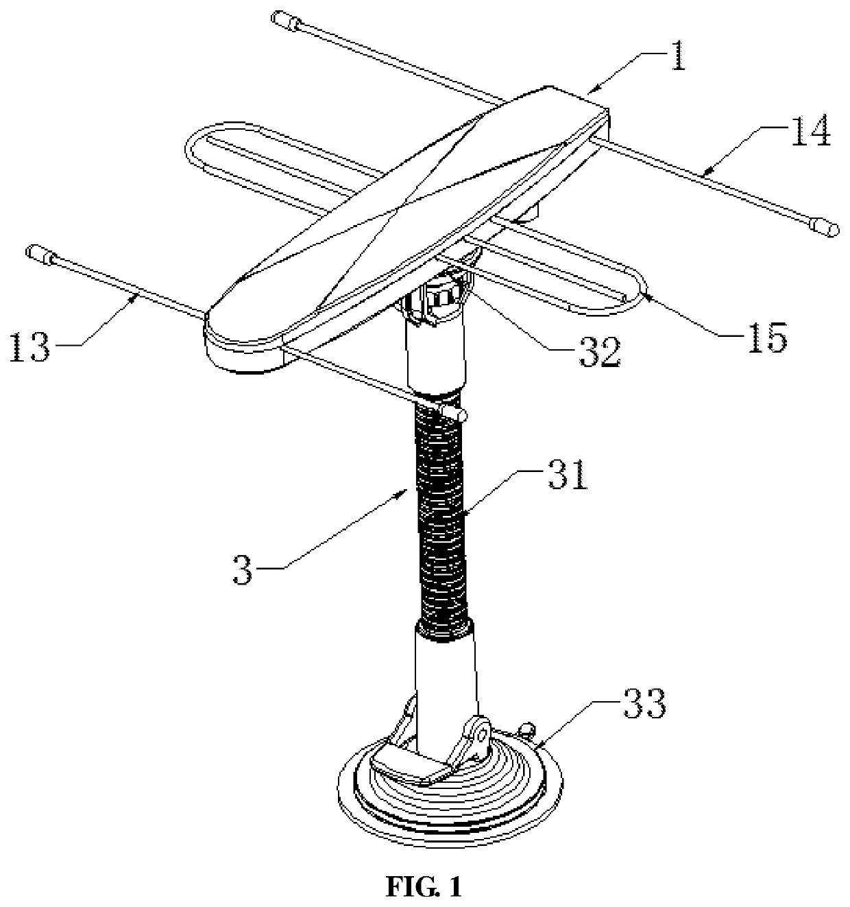
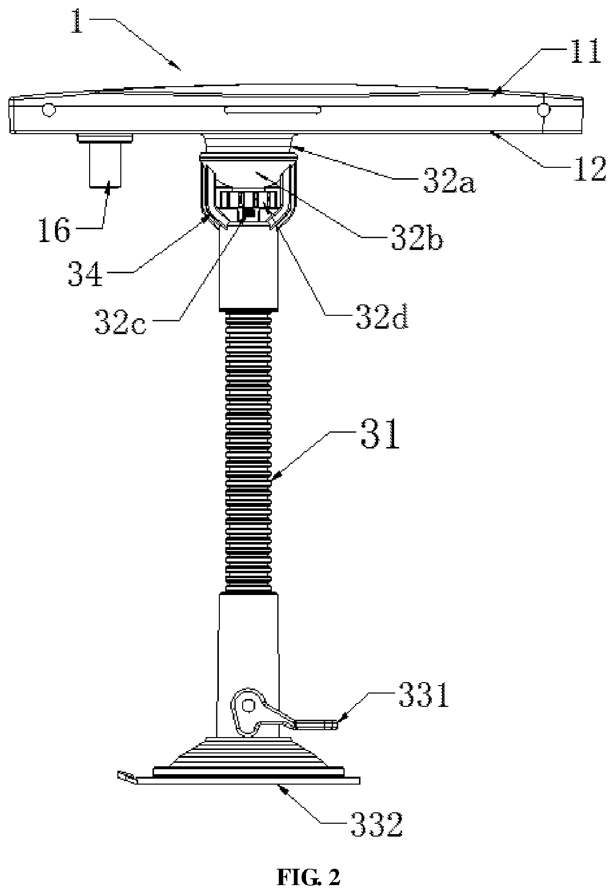
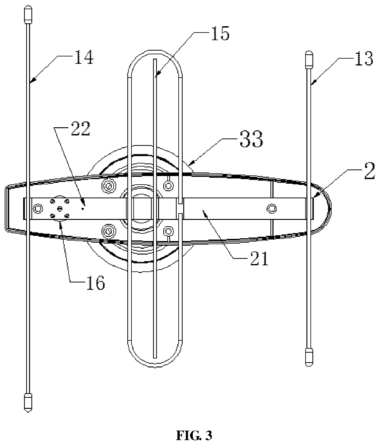
[0009]The solution of the present application is further described below in conjunction with FIGS. 1 to 3:

[0010]A small type high gain indoor Yagi antenna includes an antenna body 1, a PCB substrate 2 and an antenna bracket 3, the antenna body 1 includes an upper shell 11 and a lower shell 12 which are fastened to each other, the upper shell 11 and the lower shell 12 are sealed together to form an inner cavity containing the PCB substrate 2, the PCB substrate 2 is in a long-strip shape and includes a PCB Barron 21 and a high gain amplifier 22, one end of the PCB substrate 2 is connected to a signal director 13, and the other end thereof is connected to a signal reflector 14, a middle section thereof is connected to a main antenna oscillator 15, the signal director 13, the signal reflector 14 and the main antenna oscillator 15 are extended from the upper shell and lower shell, the portions of the signal director 13, the signal reflector 14 and the main antenna oscillator 15, which ar...


PUM


Abstract

An indoor Yagi antenna includes an antenna body, a PCB substrate and an antenna bracket. The antenna body includes an upper shell and a lower shell which form an inner cavity containing the PCB substrate including an end connected to a signal director, an end connected to a signal reflector, a middle section connected to a main antenna oscillator, the portions of the three which are electrically contacted with the PCB substrate respectively, are wrapped by the upper shell and the lower shell, the bottom surface of the lower shell is provided with a feed line terminal block connected to the PCB substrate; the antenna bracket includes a bracket rod that can be flexibly bent, the top end of the bracket rod is provided with a universal adjusting mechanism connected to the lower shell, and the bottom end of the bracket rod is provided with a bracket base.

Description

CROSS-REFERENCE TO RELATED APPLICATION[0001]This application claims priority to Chinese patent application No. 201810655028.7 filed on Jun. 23, 2018, the contents of which are incorporated herein by reference in their entirety.TECHNICAL FIELD[0002]The present invention belongs to the field of communication technology, and specifically relates to a small type high gain indoor Yagi antenna suitable for indoor installation and use.TECHNICAL BACKGROUND[0003]Due to the large size of a traditional high-gain TV Yagi antenna, the installation thereof requires a specific antenna bracket and a specific embracing rod, meanwhile, due to the directional characteristic of the Yagi antenna, it is extremely inconvenient to adjust the orientation and the angle of the antenna after installation. In addition, due to the size and shape thereof, a user can only choose to mount the antenna in an outdoor location such as a top floor of a building, an outdoor environment and various weather factors cause t...

Claims


Application Information

Patent Timeline
Patent Type & Authority Patents(United States)
IPC IPC(8): H01Q1/12H01Q19/06H01Q1/00H01Q9/16
CPCH01Q9/16H01Q1/007H01Q1/12H01Q19/06H01Q1/42H01Q1/50H01Q3/02H01Q19/02H01Q19/10H01Q19/30H01Q1/1264H01Q1/20H01Q3/04
Inventor LIU, XIAOBINGLI, QIN
Owner JIANGXI INNOVATION TECH CO LTD
Learn More