
Fresnel lens with a light receiving effect

a technology of light receiving effect and lens, which is applied in the field of lens, can solve the problems of limiting the effective working area of the first reflection surface and the second refraction surface, affecting the light receiving effect of the lens, and the radius of the first lead angle portion is too large, so as to improve the effective working area of the refraction surface and improve the light receiving

Active Publication Date: 2020-09-29
CONCRAFT HLDG
View PDF3 Cites 0 Cited by
  • Summary
  • Abstract
  • Description
  • Claims
  • Application Information

AI Technical Summary

Benefits of technology

[0006]The primary object of the present invention is to provide a Fresnel lens, and more particularly to a Fresnel lens wherein the reflection area and the refraction area are increased to improve the overall light receiving effect.
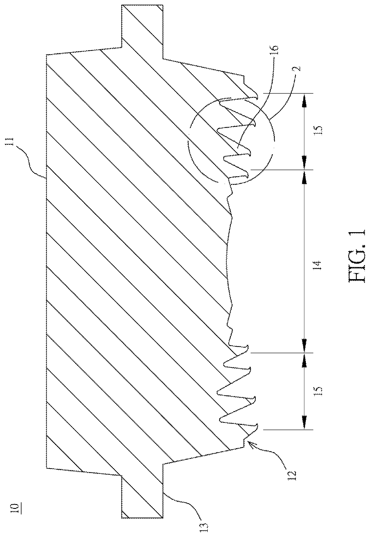
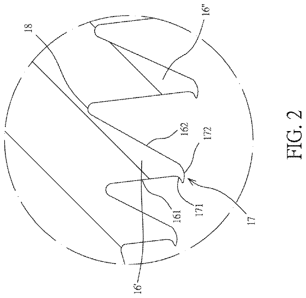
[0007]To achieve the abovementioned object, the present invention discloses a Fresnel lens with a light receiving effect. The Fresnel lens comprises a converging surface and an incidence surface opposite to the converging surface. The incidence surface is provided with an optically effective refractive region and an optically reflective region surrounding the optically effective refractive region. The optically reflective region is provided at least with a prism that is annularly disposed outside the optically effective refractive region. The prism is provided with a refraction surface in adjacent to the optically effective refractive region and a reflection surface that is disposed at a first angle relative to the refraction surface. The refraction surface is provided with a first bending section that is extended toward the optically effective refractive region, the reflection surface is provided with a second bending section that is extended toward the optically effective refractive region, and the first bending section is interconnected with the second bending section, so that an inverted hook portion is formed on a tail end of the prism using the first bending section and the second bending section, which increases the effective working area of the refraction surface and the reflection surface, thereby improving the light receiving effect of the Fresnel lens.
[0017]The present invention provides a Fresnel lens with a light receiving effect and is provided with following advantages in comparison with the prior art.
[0018]The Fresnel lens of the present invention is made of silica gel. Therefore, the inverted hook part is formed on the tail end of the prism to increase the effective working area of the refraction surface and the reflection surface, thereby providing a better light receiving effect to the optically reflective region.

Problems solved by technology

Therefore, when the first lead angle portion is formed in the plastic material, in addition to that the plastic material will be affected by the contraction in the cooling process, the plastic material will not be completely filled into the mold in the process of injection, due to the bad fluidity of the plastic material itself, thereby resulting in that the radius of the first lead angle portion is too large.
It is found from an actual measurement to the conventional Fresnel lens that the radius of the first lead angle portion is roughly between 0.02 mm and 0.025 mm, which in turn limits the effective working area of the first reflection surface and the second refraction surface, thereby affecting the light receiving effect of the Fresnel lens.

Method used


Image

  • Fresnel lens with a light receiving effect
  • Fresnel lens with a light receiving effect
  • Fresnel lens with a light receiving effect

Examples


Embodiment Construction

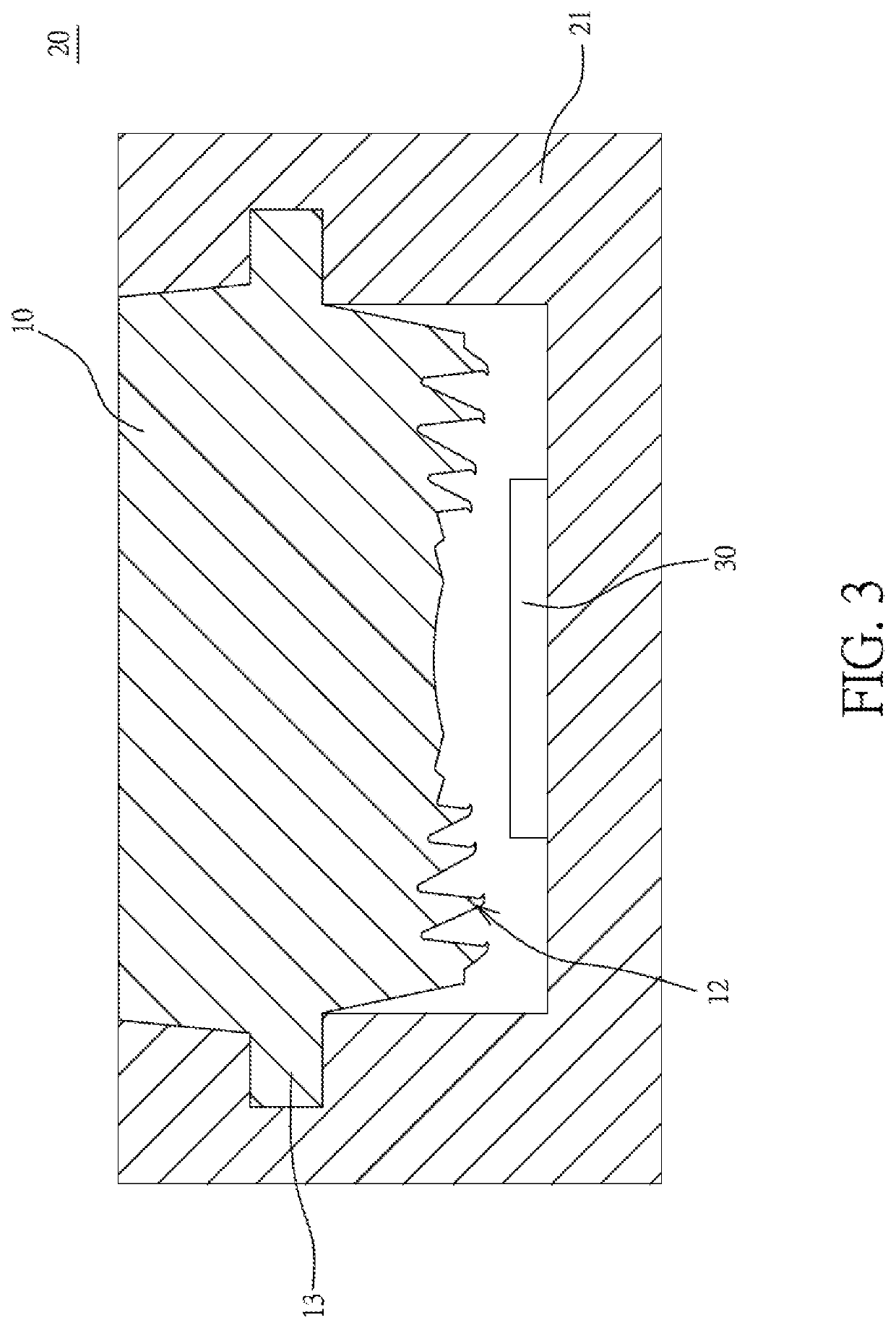
[0023]Referring to FIG. 1 and FIG. 2, the present invention discloses a Fresnel lens with a light receiving effect. In the present embodiment, a Fresnel lens 10 is formed integrally by injecting silica gel into a mold (not shown in the drawings). As silica gel itself is provided with better fluidity as compared with the abovementioned plastic material, when silica gel is injected into the mold through heating, silica gel can be filled completely into the mold, forming the Fresnel lens 10 in the present invention after silica gel is cooled down in the mold.

[0024]The Fresnel lens 10 comprises a converging surface 11, an incidence surface 12 opposite to the converging surface 11, and a positioning portion 13 that is annularly disposed between the converging surface 11 and the incidence surface 12. The incidence surface 12 is provided with an optically effective refractive region 14 and an optically reflective region 15 annularly surrounding the optically effective refractive region 14....


PUM

PropertyMeasurementUnit
radiusaaaaaaaaaa
radiusaaaaaaaaaa
radiusaaaaaaaaaa

Abstract

The present invention discloses a Fresnel lens with a light receiving effect, including a converging surface and an incidence surface opposite to the converging surface. The incidence surface is provided with an optically effective refractive region and an optically reflective region annularly surrounding the optically effective refractive region. The optically reflective region is provided at least with a prism annularly disposed outside the optically effective refractive region. The prism is provided with a refraction surface which is in adjacent to the optically effective refractive region and a reflection surface which is disposed at a first angle relative to the refraction surface. In addition, a tail end of the prism is an inverted hook part. Therefore, the effective working area of the refraction surface and the reflection surface can be increased, thereby improving the light receiving effect of the Fresnel lens.

Description

BACKGROUND OF THE INVENTIONa) Field of the Invention[0001]The present invention relates to a Fresnel lens, and more particularly to a Fresnel lens with a light receiving effect.b) Description of the Prior Art[0002]A Fresnel lens is characterized in a short focus, high luminous flux and light in weight. In addition, the application of Fresnel lens is very wide; in particular, the Fresnel lenses are largely used on flashlights in existing smartphones to increase the projected angles of light of the flashlights.[0003]The Fresnel lens applied on the flashlight of the existing smartphone is primarily formed by injection molding to a plastic material, and the Fresnel lens includes a converging surface and an incidence surface. The incidence surface is provided with an optically effective refractive region and at least an optically reflective region surrounding the optically effective refractive region. The optically reflective region includes a first prism that is annularly disposed outsi...

Claims


Application Information

Patent Timeline
Patent Type & Authority Patents(United States)
IPC IPC(8): G02B3/08B29D11/00B29K105/00
CPCG02B3/08B29D11/00269B29K2105/0061
Inventor TSAI, TZU-CHINGCHEN, JIE-RU
Owner CONCRAFT HLDG
Learn More