Intelligent solar distributed power station illumination energy-saving system

An energy-saving system and distributed technology, applied in the field of lighting, can solve the problems of low energy distribution density, consume a lot of financial and material resources, reduce the use effect, etc., and achieve the effect of improving the road usage rate, ensuring the charging supply, and miniaturizing the overall structure.

Active Publication Date: 2016-09-28
厦门市美亚睿进电力科技有限公司
View PDF7 Cites 0 Cited by
  • Summary
  • Abstract
  • Description
  • Claims
  • Application Information

AI Technical Summary

Problems solved by technology

[0003] However, in use, the energy distribution density that it needs to irradiate is small, that is, it will occupy a huge area, and because the conversion efficiency of photovoltaic equipment is generally not high today, it can only be arranged in a way that replaces quality with quantity. Nowadays, photovoltaic power generation is generally built in the sun In an open area that is sufficient but sparsely populated, power generation is formed by laying photovoltaic power generation devices on a large area of ​​land. However, due to geographical problems, the obtained electric energy can only be transmitted in parallel with the grid. It takes a lot of financial and material resources to set up the grid. There is also a certain loss in power transmission, which greatly reduces its use effect

Method used


Image

  • Intelligent solar distributed power station illumination energy-saving system
  • Intelligent solar distributed power station illumination energy-saving system
  • Intelligent solar distributed power station illumination energy-saving system

Examples


Embodiment 1

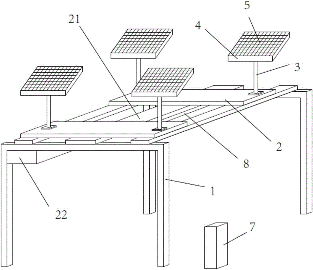
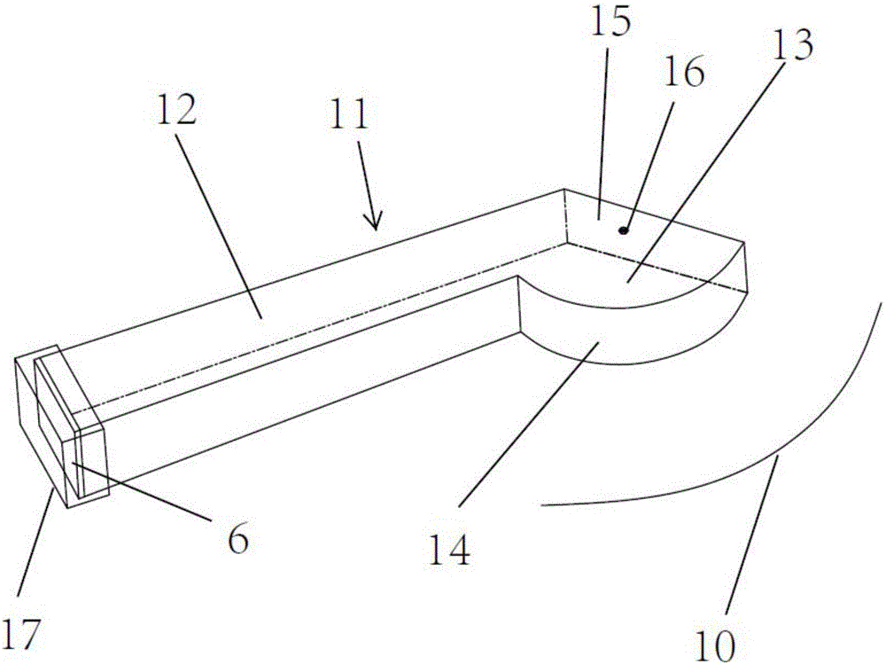
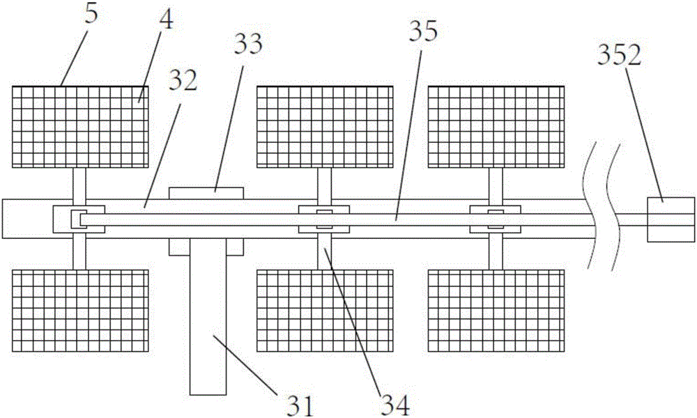
[0026] refer to Figure 1 to Figure 4 As shown, the intelligent solar energy distributed power station lighting energy-saving system includes several gantry frames 1 set on the road surface. A number of base support frames 3 are arranged on the beam frame, and a number of bearing frames 4 are arranged on the base support frame, and a number of concentrating assemblies 5 are evenly arranged in the carrying frame, and the concentrating assemblies are connected with the photoelectric conversion device 6, and the photoelectric conversion device and the electric energy storage The device 7 is connected, the electric energy storage device is connected with the light belt 8, and the light belt is supplied with electricity. The light belt is set at the bottom of the gantry frame, and can be set in the center of the gantry frame. The light source of the light belt covers a wide area, which can ensure that there is light on the side of the road , will not cause blind spots to the line o...

Embodiment 2

[0042] The difference between Embodiment 2 and Embodiment 1 is that it includes a monitoring probe that monitors the road conditions under the gantry, and the monitoring probe is also connected to a motion detection device. The motion detection device triggers the switch by judging the movement of vehicles, pedestrians or ships. The controller turns on the light strip to provide lighting to prevent the poor sight caused by the occlusion of the concentrating components on the road surface. This method avoids the construction of ground induction coils on the ground, and is also suitable for river channels, with strong versatility.


PUM


Abstract

The invention discloses an intelligent solar distributed power station illumination energy-saving system comprising a plurality of portal frames arranged on a pavement. Cross-beam frames are erected on the tops between the adjacent portal frames; a plurality of pedestal support frames are arranged on the cross-beam frames; a plurality of bearing frames are arranged on the pedestal support frames; a plurality of condensation assemblies are arranged uniformly in the bearing frames and are connected with photoelectric conversion devices; the photoelectric conversion devices are connected with electric energy storage devices connected with light bands; and the light bands are arranged at the bottoms of the portal frames. Switch controllers are arranged between the light bands and the electric energy storage devices. According to the invention, with the condensation assemblies having high conversion efficiency, the equipment size is reduced; little setting geographic restriction exists; power transmission can be carried out conveniently; power losses are reduced; and the usage rate is improved.

Description

technical field [0001] The invention relates to the lighting field, in particular to an intelligent solar energy distributed power station lighting energy-saving system. Background technique [0002] Photovoltaic power generation technology is a technology that directly converts solar energy into electrical energy, called photovoltaic power generation technology, which is a green energy project encouraged by the state. It has great advantages: 1. No risk of depletion; 2. Safe and reliable, no noise, no pollution emissions, absolutely clean (no pollution); 3. No need to consume fuel and erect transmission lines to generate power on the spot; 4. High energy quality; 5. Short construction period and short time to obtain energy. [0003] However, in use, the energy distribution density that it needs to irradiate is small, that is, it will occupy a huge area, and because the conversion efficiency of photovoltaic equipment is generally not high today, it can only be arranged in a...

Claims


Application Information

Patent Timeline
Patent Type & Authority Applications(China)
IPC IPC(8): H02S40/22H02S20/30H02S20/32H02S10/20F21S4/20F21S9/04F21W131/103
CPCF21S9/04F21W2131/103H02S10/20H02S20/30H02S20/32H02S40/22Y02B20/72Y02E10/52Y02E70/30
Inventor 叶剑锋叶萌竹
Owner 厦门市美亚睿进电力科技有限公司
Why Eureka
Try Eureka