Reactive automated guided vehicle vision guidance system

a technology of automatic guided vehicles and guidance systems, applied in the direction of process and machine control, distance measurement, instruments, etc., can solve the problems of complex system development and implementation, and achieve the effects of low cost, constant lighting condition, and enhanced customer understanding and therefore use of the system

Inactive Publication Date: 2006-03-23
CYCLE TIME CORP
View PDF19 Cites 146 Cited by
  • Summary
  • Abstract
  • Description
  • Claims
  • Application Information

AI Technical Summary

Benefits of technology

[0008] The above objects are achieved with the reactive AGV vision guidance system according to the present invention. The present invention includes an AGV vision guidance system that places the camera system and controlled lighting sources between the drive wheels of the AGV to shield from ambient light and provide a constant lighting condition. The AGV guide path includes physical path properties for controlling AGV behavior. Visual Parameters of the guide path such as line thickness, line color, the presence and form of a secondary control line, or the presence of distinct line elements may all be used as visual input control signals for the AGV. Additionally viewable icons are used for controlling AGV routing. These icons may, preferably, also be human readable to enhance the customer understanding and therefore usage of the system. The system according to the present invention provides a purely reactive low cost, easily implemented AGV system minimizing initial installation costs and concerns as well as making post installation modifications essential trivial. Further the reactive AGV system according to the present invention more easily communicates its operation to those in its working environment and is therefore more readily accepted by those in its work environment.

Problems solved by technology

These systems are complex to develop and to implement.

Method used


Image

  • Reactive automated guided vehicle vision guidance system
  • Reactive automated guided vehicle vision guidance system
  • Reactive automated guided vehicle vision guidance system

Examples


Embodiment Construction

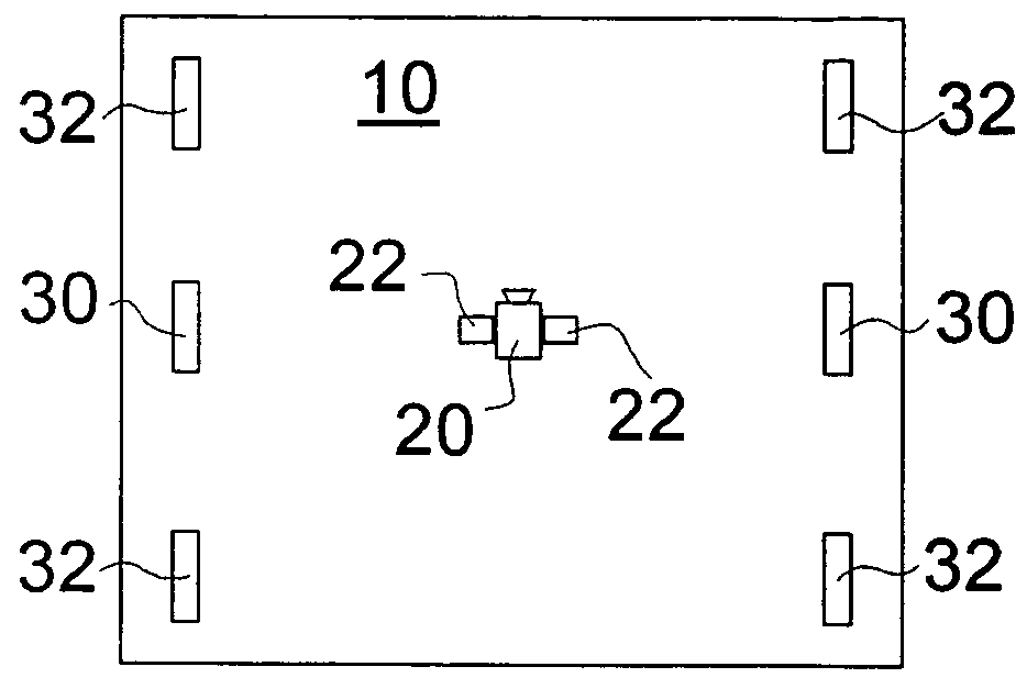
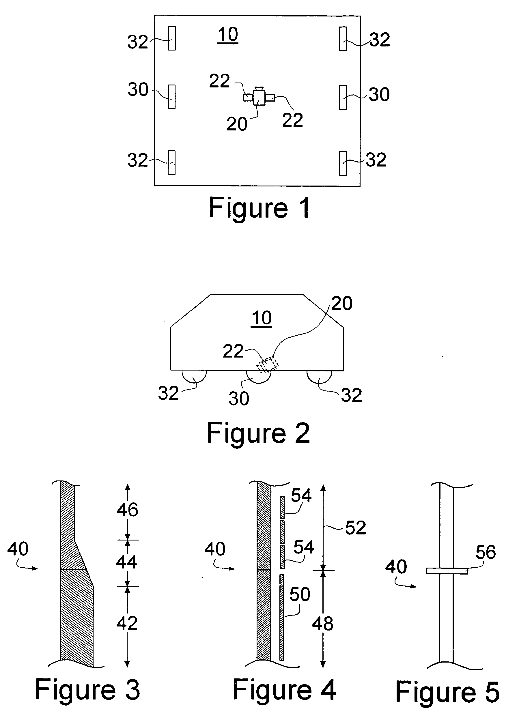
[0025]FIGS. 1 and 2 schematically illustrate an AGV vision guidance system according to one aspect of the present invention. As discussed above, existing vision based guidance systems for AGVs are vulnerable to error from changing ambient or reflected light especially from changing sun conditions in windowed corridors. The AGV vision guidance system of the present invention minimizes this weakness through the placement of the vision system relative to the robot body 10. Specifically, as shown in the FIGS. 1 and 2 the camera system 20 is placed between the drive wheels 30 of the AGV. There is no limitation on where the drive wheels 30 of a given AGV are located. Some are centrally mounted (as shown in the figures), and may include further wheels 32 in front or behind (with either wheels 30 or 32 being steered). The AGV may have the drive wheels 30 in the back of the vehicle with a pair, or a single central wheel 32 in the front. The AGV may further have the drive wheels 32 in the fro...


PUM


Abstract

A reactive AGV system includes an AGV vision guidance system which places the camera system and controlled lighting sources between the drive wheels of the AGV to shield from ambient light and provide a constant lighting condition. The AGV guide path includes physical path properties for controlling AGV behavior. Visual Parameters of the guide path such as line thickness, line color, the presence and form of a secondary control line, or the presence of distinct a line elements may all be used as visual input control signals for the AGV. Additionally viewable icons are used for controlling AGV routing. These icons may, preferably, also be human readable to enhance the customer understanding and therefore usage of the system.

Description

RELATED APPLICATION [0001] The present application claims the benefit of provisional patent application Ser. No. 60 / 611,953 filed Sep. 22, 2005 and entitled “Reactive Automated Guided Vehicle Vision Guidance System”.BACKGROUND INFORMATION [0002] 1. Field of the Invention [0003] The present invention relates to vision systems for Automated Guided Vehicles (AGVs), and more particularly to vision system placement of a reactive AGV and communicating control signals to the reactive AGV and to those around the AGV. [0004] 2. Prior Art [0005] Automatic Guided Vehicles have been used to transport materials for many years. One method for guiding these vehicles is to utilize complex robotic vehicle positioning systems such position locating tags / beacons, or other sensors, or even GPS systems (which is of limited use in indoor environments) together with the knowledge of a world map in the robotic vehicle. These systems are complex to develop and to implement. Another system has been the place...

Claims


Application Information

Patent Timeline
Patent Type & Authority Applications(United States)
IPC IPC(8): G01C22/00
CPCG05D1/0246G05D2201/0216
Inventor THORNE, HENRY F.
Owner CYCLE TIME CORP
Why Eureka
Try Eureka