Cooling fan

Inactive Publication Date: 2005-06-16
HUANG CHENG YU
9 Cites 136 Cited by

AI-Extracted Technical Summary

Problems solved by technology

Since the computer related peripherals have been continuously researched and innovated, the connecti...

Benefits of technology

[0008] The present invention provides a mini cool fan capable of connecting to any outlets of the USB, 1394 and PS2, characterized in that there is a fan inside the cool fan case. Its power line ends have the plugs of the USB, 1394 and PS2 to connect to arbitrary outlets of mobile computer, c...

Abstract

The present invention discloses a cooling fan having electrical power drawing from the computer, its power line ends have the plugs of the USB, 1394 and PS2 to connect to arbitrary outlets of mobile computer, computer host, or the hub of the USB, 1394 and PS2. The cooling fan includes a basis, a front shell, a rear shell, a fan set, a speed tuner, a power signal line and a connecting plug. The cooling fan also has a recess on the bottom of front side of the basis to support individual card reader, HUB, hard disk or radio device, and additionally has a signal line and plug for connecting to the computer.

Application Domain

Technology Topic

Image

  • Cooling fan
  • Cooling fan
  • Cooling fan

Examples

  • Experimental program(1)

Example

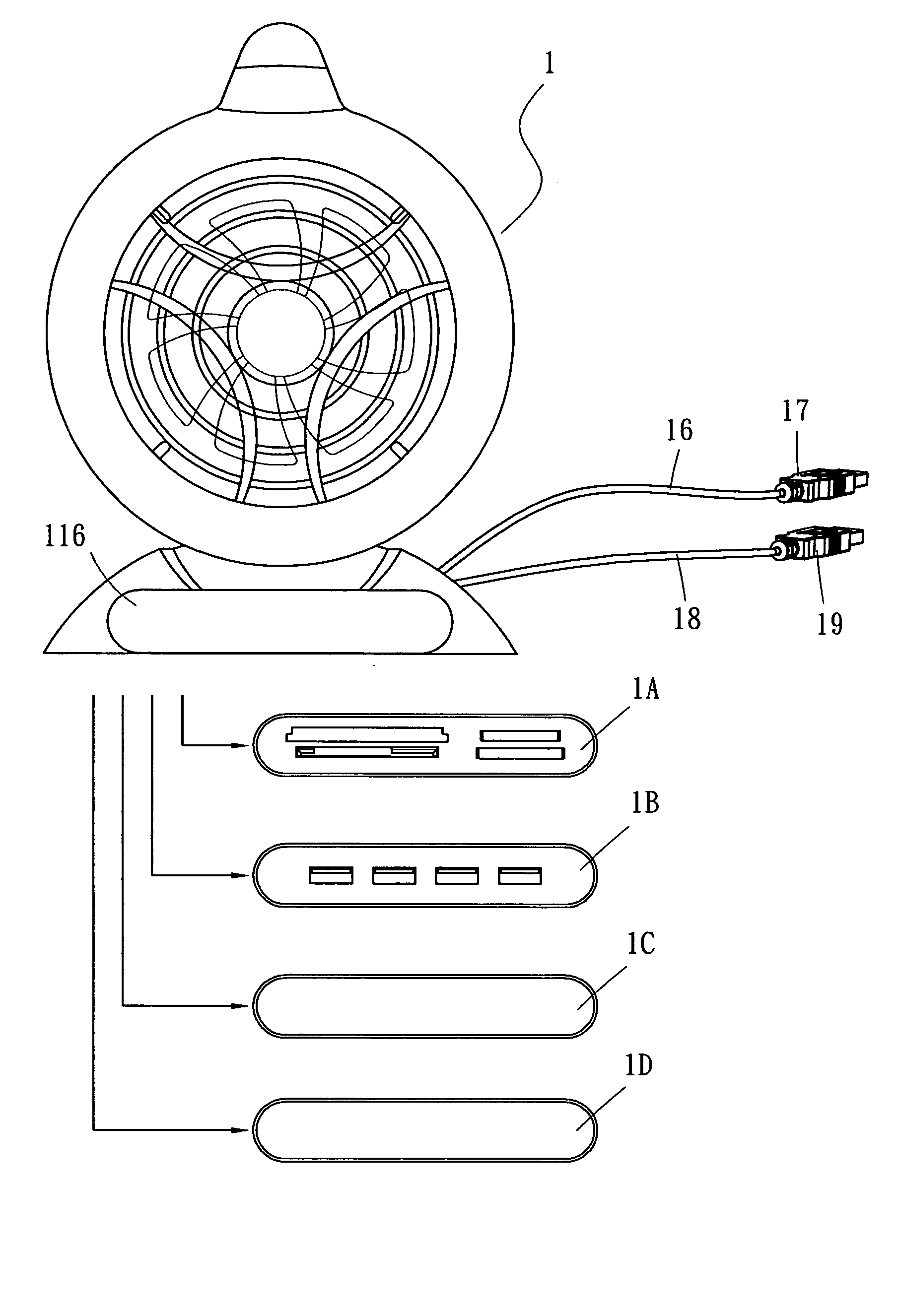
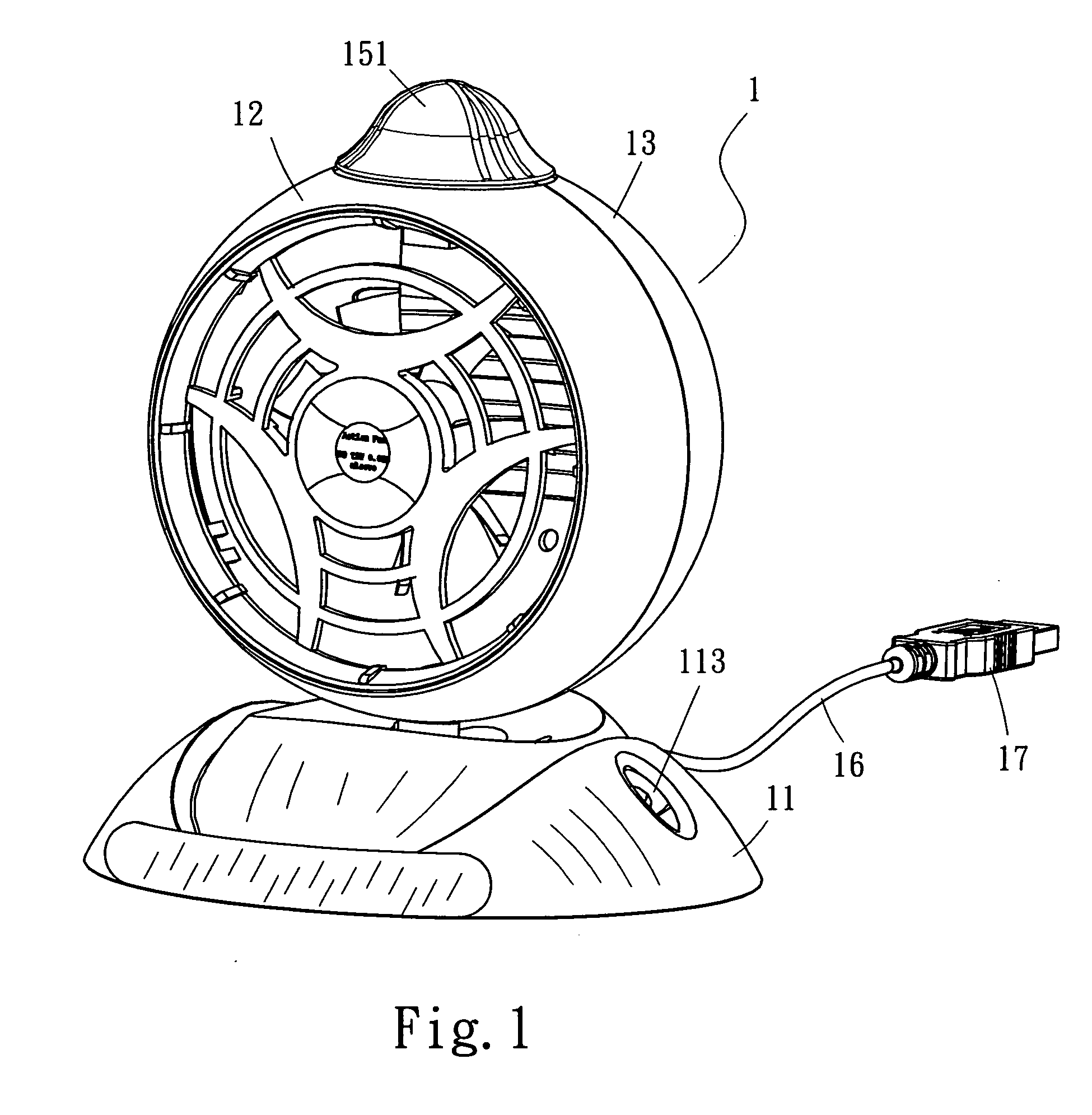
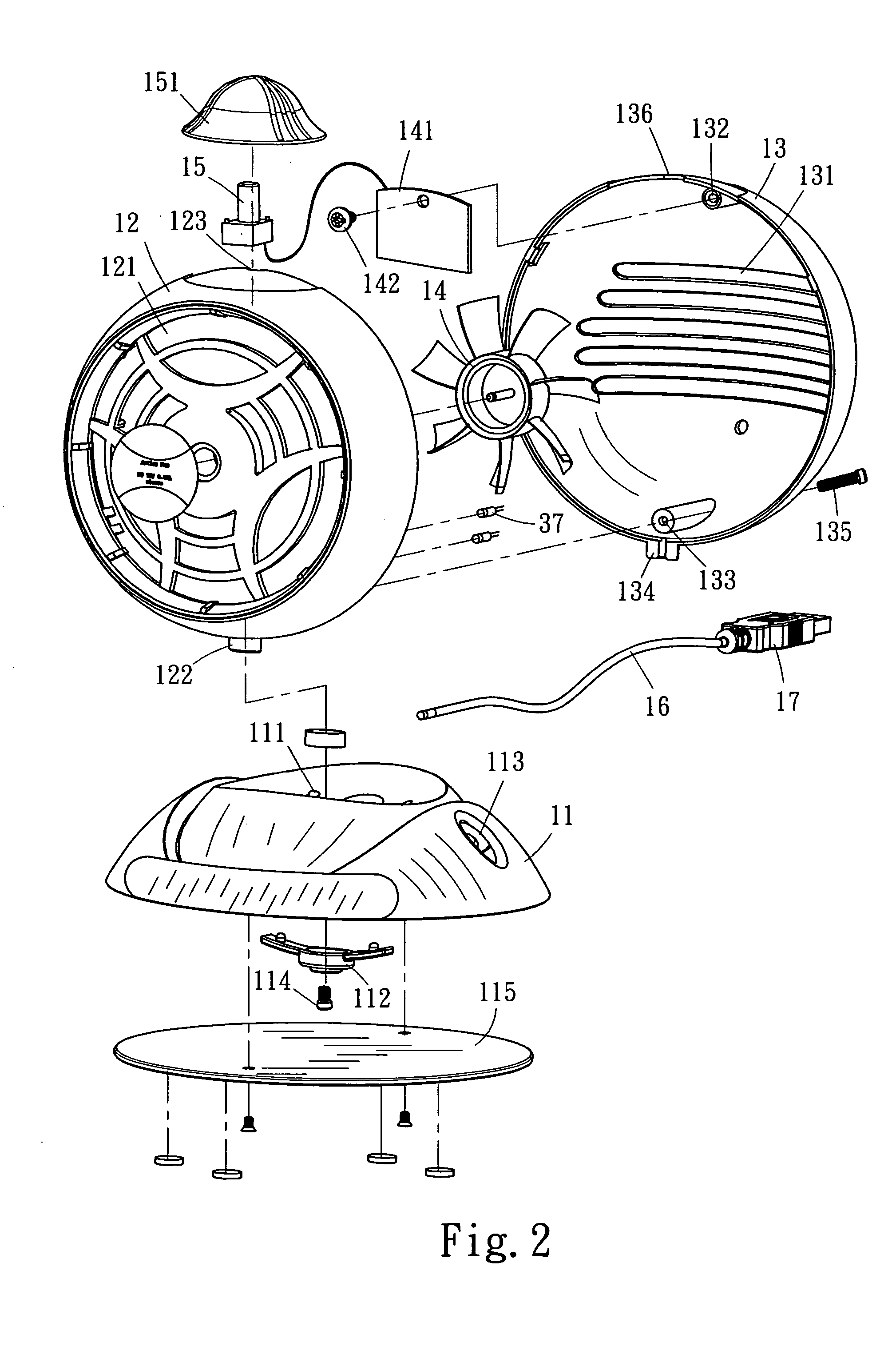
[0012] Referring to FIG. 1 and FIG. 2, the present invented cool fan (1) includes a basis (11), a front shell (12), a rear shell (13), a fan set (14), a speed tuner (15), a power signal line (16) and a connecting plug (17).
[0013] The basis (11) has an adjustable positioning hole (111), a positioning reed (112) on the bottom and a pen stand (113) on the side.
[0014] There fixed a fan set (14) on the center inside the front shell (12) and has a blowing net (121) on the front rim, also there is a half circle thread of a screw (122) on the bottom of the front shell (12), and there is a inlet (131) on the back of the rear shell (13), its inner proper position places screw threads (132), (133) and a half circle screw thread (134).
[0015] The PCB (141) board of a controlled fan set (14) is fixed by a screw (142) on the screw thread (132) of the rear shell (13). After binding both the front shell (12) and rear shell (13) by a screw (135) being screwing into a ball shape, the PCB board (141) connecting to a signal line (16) draws out from the back of the rear shell (13) and having connecting plug (17) on its line end.
[0016] The basis (11) described above uses a screw (114) screwing through the positioning reed (112) and into the half circle screw threads (122) and (134) on the bottom of both the front shell (12) and the rear shell (13) to form a ball-shaped combination. The elevation angle of the cool fan (1) is adjustable by the positioning reed (112) and there covers a bottom board (115) on the basis (11) bottom.
[0017] The contact top of the front shell (12) and the rear shell (13) described above has holes (123) and (136) to fix the position of rotating speed tuner, and there is an arc knob (151) placed on the top for the user to adjust and control rotating speed of the fan (14). The fan (14) is capable of with light (the current fan suppliers provide fans with light), or additionally places an LED light (137) inside the front shell (12) to have a lighting effect for the front shell (13) of the present invention while turn-on the cool fan (14). Accordingly, the present invented cool fan (1) is to use the USB, 1394 and PS2 plugs (17) connecting to the outlets of the computer or hub to offer the cool fan (1) for work. The lighting appearance from the fan (14) has technical and secret feel, also the arc knob (151) can adjust rotating speed of the fan (14).
[0018] AS FIG. 2 shown, the present invented cool fan (1) places a recess (116) on the bottom of front side of the basis (11) to support individual card reader (1A), HUB (1B), hard disk (1C) or radio device (1D), and meanwhile, the apparatus additionally has a signal line (18) and plug (19) for connecting to the computer in order to increase its function and flexibility.
[0019] The connecting plug (17) and plug (19) described above can be the connecting terminal of the USB, 1394 and PS2.

PUM

no PUM

Description & Claims & Application Information

We can also present the details of the Description, Claims and Application information to help users get a comprehensive understanding of the technical details of the patent, such as background art, summary of invention, brief description of drawings, description of embodiments, and other original content. On the other hand, users can also determine the specific scope of protection of the technology through the list of claims; as well as understand the changes in the life cycle of the technology with the presentation of the patent timeline. Login to view more.

Similar technology patents

Method for preparing polypeptide fruit jelly

InactiveCN1864528AEasy to carryIncrease usageVegetable proteins working-upNutrientBoiling point
Owner:CHINA RES INST OF DAILY CHEM IND

Floating leisure platform

InactiveUS20060162637A1Increase usageIncrease attractivenessLife-buoysRaftsMarine engineeringIngested food
Owner:ZEUS

Classification and recommendation of technical efficacy words

Why Eureka
Try Eureka