
System to transfer people and/or cargo during offshore operations

a technology for offshore operations and people, applied in the direction of load-engaging elements, ship accessories, vessel parts, etc., can solve the problems of large and heavy hydraulic actuator systems that are also low energy efficiency, relative movements cannot be fully compensated by the actuator system, and the weight is too high, so as to reduce the weight and improve the performance of the entire system. , the effect of less sensitive to wind forces

Active Publication Date: 2020-10-06
EAGLE ACCESS BV
View PDF9 Cites 0 Cited by
  • Summary
  • Abstract
  • Description
  • Claims
  • Application Information

AI Technical Summary

Benefits of technology

The system significantly reduces undesired relative movements by a factor of ten, enables quick and accurate transfer operations, reduces forces applied to the support object, and allows for transfers in adverse conditions, with the potential for reduced energy consumption and lower damage risk.

Problems solved by technology

Prior art systems are usually based on telescopically extendable gangways, but have the disadvantages that they are heavy in weight and that expensive, large and heavy hydraulic actuator systems have to be used that are also low energy efficient.
A further disadvantage of the telescopically extendable gangways may be that, due to their large weight and heavy drives, relative movements cannot be fully compensated by the actuator system.
As a result thereof the telescopically extendable gangway requires a physical connection to the platform during the transfer to compensate for the relative movements the actuator system cannot compensate for thus applying considerable and undesired connection forces to the platform.
The required physical connection can only be made using a costly specially constructed so-called “landing station”.
This may have the additional disadvantage that in case of erroneous control of the system or the vessel carrying it, e.g. in case of drift of the vessel, very high forces may be applied to the platform or damage is caused.
Another disadvantage of the telescopically extendable gangways may be that establishing the transfer connection before it is ready for the transfer of people or loads requires considerable time.
The same may apply to the retrieval of the gangway, which may take considerable time in which no other activity can take place and which may undesirably add to the time a vessel has to maintain its position.
Yet another disadvantage of the telescopically extendable gangways may be that people have to walk over the gangway, which most of the time is sloped and telescoping while walking over the gangway.
This may not be entirely safe.
Yet a further disadvantage of the telescopically extendable gangways may be that they have a limited reach of the free end of the telescopically extendable gangway thus requiring a vessel to maintain its position near a platform to a high degree of accuracy and thus limiting the conditions of weather and waves under which a safe transfer is possible.
A further disadvantage of the telescopically extendable gangways may be that in case a transfer is required to a relatively high location, the entire system usually has to be lifted from the vessel's deck with a rigid, heavy and expensive construction.
Another disadvantage of the telescopically extendable gangways may be that the system requires a lot of space, not only for the constructional components of the system, but also for the separate external hydraulic systems usually provided inside standard transport containers.
A disadvantage herewith is that the dynamic compensation is relatively slow and inaccurate.
A long hydraulic chain of motion sensors, software, control equipment, lines, pumps, accumulators, valves, switches, driving engines / actuators, make it impossible in practice to keep a tip of the boom with the capsule connected thereto sufficiently still relative to movements of the vessel.
Considerable residual movements always remain at the “compensated” tip which make the placing of the capsule onto the platform very risky.
Another disadvantage is that in GB 2 336 828 the dynamic compensation for roll, pitch and heave is based upon the gimbal arrangement between the arm and the deck mounting.

Method used


Image

  • System to transfer people and/or cargo during offshore operations
  • System to transfer people and/or cargo during offshore operations

Examples


Embodiment Construction

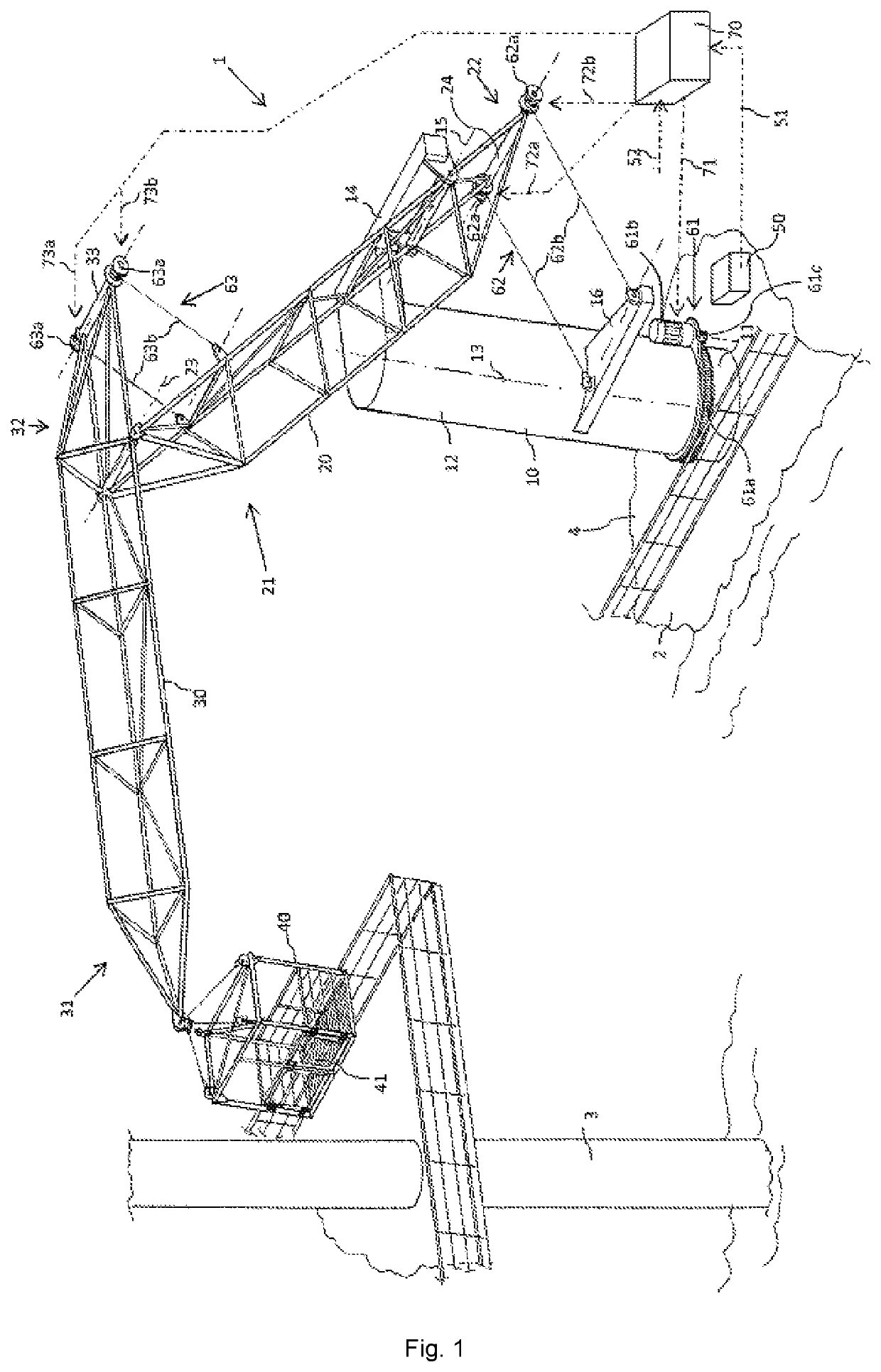
[0085]FIG. 1 depicts a system 1 for transferring people and / or cargo during offshore operations according to an embodiment of the invention. Offshore operations may include the transfer of people and / or cargo from a vessel 2 to a fixed construction 3, e.g. a platform or other fixed offshore installation, and / or vice versa. However, offshore operations may also include transfer of people and / or cargo between two vessels, and rescue or recovery operations to retrieve people and / or cargo from the water. Hence, system 1 is preferably used in cases in which there are undesired relative movements between two objects preventing an easy transfer of people and / or cargo.

[0086]In this embodiment, the system is mounted on a deck 4 of the vessel 2, but alternatively, the system 1 could have been mounted on the fixed construction 3.

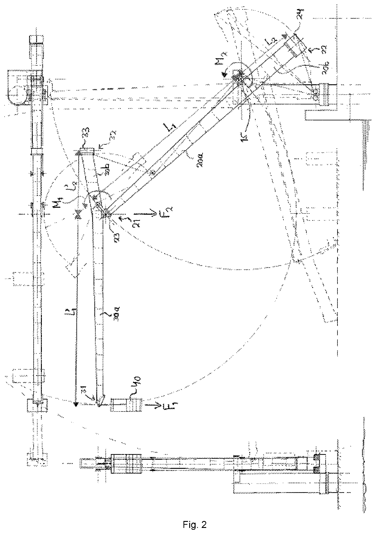
[0087]The system 1 comprises a base 10, a support arm 20, a boom 30, a load support element 40, a measurement system 50, an actuator system, and a control system 70.

[0...


PUM


Abstract

A system to transfer people and / or cargo during offshore operations includes a base with a stationary part and a moveable part that is rotatable relative to the stationary part about a substantially vertical first axis; a support arm having a first free end and a second free end opposite the first free end of the support arm; a boom having a first free end and a second free end opposite the first free end of the boom; a load support element; a measurement system; an actuator system; and a control system. The support arm at a location in between the first and second free end of the support arm is mounted to the moveable part of the base such that the support arm is rotatable relative to the moveable part about a substantially horizontal second axis.

Description

CROSS-REFERENCE TO RELATED APPLICATIONS[0001]This application is the National Stage of International Application No. PCT / NL2017 / 050538, filed Aug. 15, 2017, which claims the benefit of Netherlands Application No. NL 2017314, filed Aug. 15, 2016, the contents of which is incorporated by reference herein.FIELD OF THE INVENTION[0002]The invention relates to a system to transfer people and / or cargo between two objects moving relative to each other, e.g. as encountered in offshore operations, in particular in a safe manner by compensating relative movements between the two objects.BACKGROUND OF THE INVENTION[0003]With the increasing number of offshore platforms and offshore wind turbines, the need for an easy and cheap system to transfer people and / or cargo to and from these offshore platforms and wind turbines, e.g. for maintenance and installation purposes, has increased.[0004]Prior art systems are usually based on telescopically extendable gangways, but have the disadvantages that the...

Claims


Application Information

Patent Timeline
Patent Type & Authority Patents(United States)
IPC IPC(8): B63B27/10B66C23/76B66C13/22B63B27/30B66C23/53B63B27/16B63B17/00
CPCB63B27/30B63B27/10B66C23/76B66C13/22B66C23/53B63B27/16B63B2017/0072
Inventor PRINS, WILLEM FREDERIK
Owner EAGLE ACCESS BV
Learn More