Dielectric collimator with a rejecting center lens

a technology of center lens and dielectric collimator, which is applied in the direction of instruments, lighting and heating apparatus, lighting support devices, etc., can solve the problems of unwanted light, center lens, especially, and too much etendue in the center lens section, so as to reduce etendue, reduce or even completely remove the halo effect

Active Publication Date: 2020-10-06
SIGNIFY HLDG BV
View PDF12 Cites 0 Cited by
  • Summary
  • Abstract
  • Description
  • Claims
  • Application Information

AI Technical Summary

Benefits of technology

[0007]It is an object of the present invention to overcome this problem, and to provide a dielectric collimator which in use exhibits a reduced etendue and thereby reducing or even completely removing the halo effect caused by the proximity of the lens to the source.

Problems solved by technology

This is in general not wanted because a clear source image makes any non-uniform feature of the LED visible on a target surface, such as bond wires, sharp edges, color differences and the like.
Such light is in many cases unwanted, because it creates a halo around the main beam.
The center lens, especially because of its imaging characteristics, is problematic when used with chips on board (COB) light sources or mid power light sources, because the edge of such light sources emits fully converted yellowish light.
The center lens puts such light at the edge of the light distribution, thus creating a yellow outermost ring around the light distribution with leads to complaints.
In other words, there is too much etendue in the center lens section.
However, besides the reduction of efficiency of the lens, the introduction of an absorbing element means an extra step in production, in the form of an injection molded part of a second material, an inserted part or some kind of a printing or painting process.
This added cost is not desirable.

Method used


Image

  • Dielectric collimator with a rejecting center lens
  • Dielectric collimator with a rejecting center lens
  • Dielectric collimator with a rejecting center lens

Examples


Embodiment Construction

[0050]The present invention will now be described more fully hereinafter with reference to the accompanying drawings, in which currently preferred embodiments of the invention are shown. This invention may, however, be embodied in many different forms and should not be construed as limited to the embodiments set forth herein; rather, these embodiments are provided for thoroughness and completeness, and fully convey the scope of the invention to the skilled person.

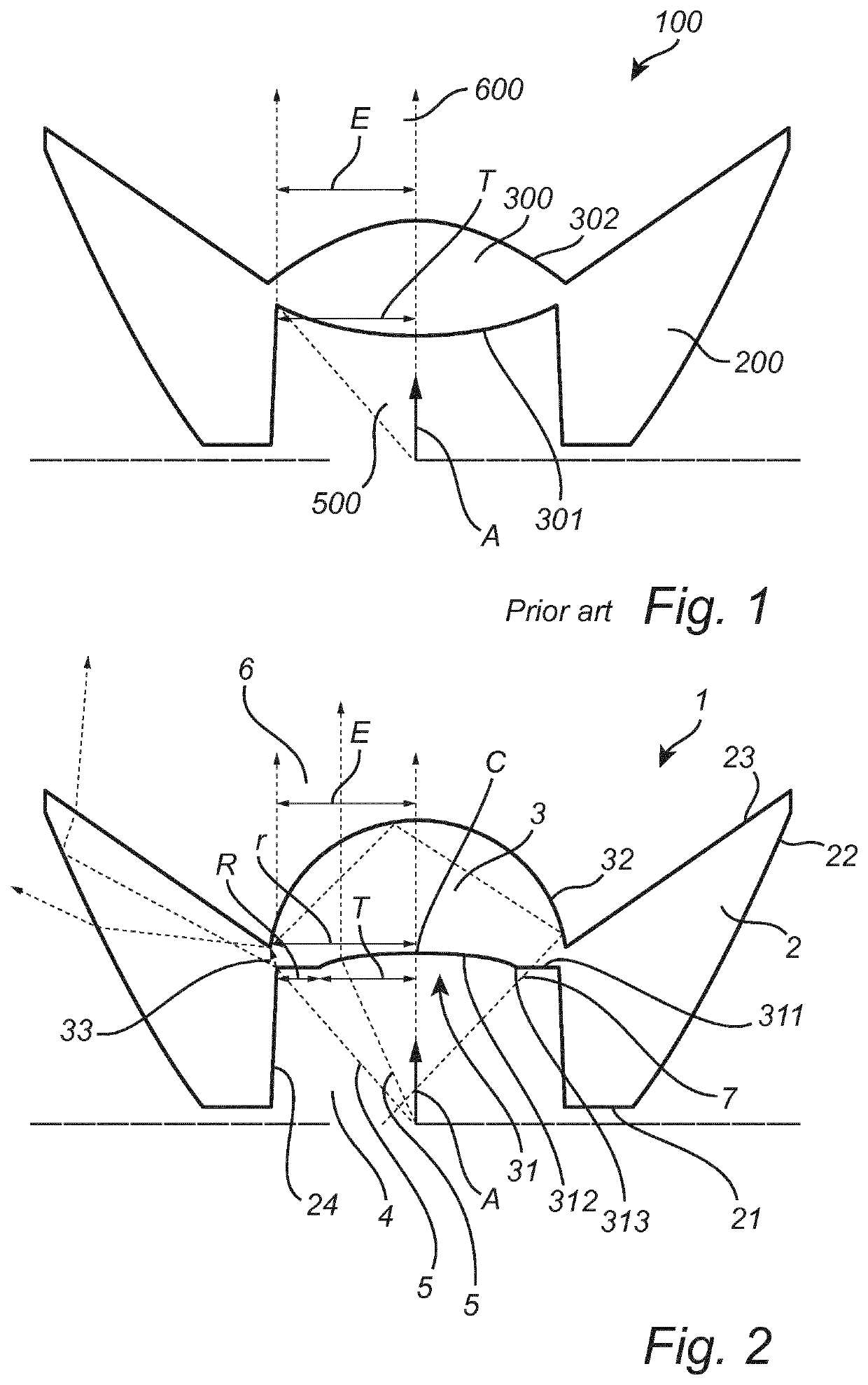
[0051]For the sake of reference, FIG. 1 shows a cross sectional side view of a prior art TIR collimator 100. The TIR collimator 100 comprises a center lens 300 and a TIR collimating outer section 200. The center lens 300 comprises a light input surface 301 and a light exit surface 302. The light exit surface 302 is convex curvature, which is typical for prior art types of TIR collimators. It is noted that spherical and aspheric light exit surfaces are possible and common, too. The light input surface 301 is also convex, and...


PUM

PropertyMeasurementUnit
angleaaaaaaaaaa
refractive indexaaaaaaaaaa
draft angleaaaaaaaaaa

Abstract

A dielectric collimator (1) comprising a center lens (3), the center lens comprising a light input surface (31) and a light exit surface (32), the light exit surface (32) being convex and substantially hemispherical, and the light input surface (31) comprising a central surface section (312) forming a light transmitting portion of the center lens adapted for receiving incoming light (5) and transmitting it to be emitted from the light exit surface, and a peripherally extending, annular outer surface section (311) being substantially plane and adapted for redirecting incoming light (5) in such a manner that the redirected light (7) undergoes TIR at the light exit surface and is emitted back out of the light input surface.

Description

FIELD OF THE INVENTION[0001]The invention concerns a dielectric collimator comprising a center lens, the center lens comprising a light input surface and a light exit surface.BACKGROUND OF THE INVENTION[0002]Dielectric collimators, and in particular TIR collimators, are the workhorses of LED lighting. Many variants are used and literally billions produced every year. TIR collimators have two sections, a section working by total internal reflection (TIR), also known as a TIR section, and a center section that is basically a lens focusing light by two refractions. In a typical design 30 to 40% of the light travels through the center lens and the rest of the light through the TIR section.[0003]For example, U.S. Pat. No. 8,371,710 B2 describes a lens for a flashlight, the lens albeit being adapted for focusing light essentially having the structure of the above-mentioned prior art types of TIR collimators. The lens comprises a lens body with a front face, a rear void, and a side surface...

Claims


Application Information

Patent Timeline
Patent Type & Authority Patents(United States)
IPC IPC(8): F21V21/00F21V7/00F21V5/04F21V5/00G02B19/00
CPCG02B19/0028F21V5/045F21V7/0091G02B19/0061F21V5/006F21L4/027F21V5/04F21V5/048
Inventor DROSS, OLIVER
Owner SIGNIFY HLDG BV
Why Eureka
Try Eureka