High efficiency lighting system, scrolling unit and projection system employing the same

a lighting system and high-efficiency technology, applied in the direction of lighting and heating apparatus, picture reproducers using projection devices, instruments, etc., can solve the problems of difficult assembly of single-panel projection systems, difficulty in arranging optical axes, etc., to reduce etendue, compact optical systems, and easy manufacturing of optical systems

Inactive Publication Date: 2008-05-06
SAMSUNG ELECTRONICS CO LTD
View PDF37 Cites 2 Cited by
  • Summary
  • Abstract
  • Description
  • Claims
  • Application Information

AI Technical Summary

Benefits of technology

[0014]The present invention provides a lighting system which reduces the etendue of a light source to achieve an easy manufacture of an optical system, to obtain a compact optical system, and to increase light efficiency, and a projection system adopting the lighting system.
[0016]The present invention also provides a compact single-panel projection system which has an improved light efficiency by adopting a scrolling unit.
[0040]According to still yet another aspect of the present invention, there is provided another compact single-panel projection system including a light source, an optical splitter, at least one scrolling unit, and a light valve. The optical splitter splits light emitted from the light source according to wavelength. The at least one scrolling unit has at least one lens cell. The lens cell has an incident side and an emitting side and divides incident light into light beams. The rotation of the lens cell causes a rectilinear motion of the light beams to achieve scrolling of incident light. The light emitted from the light source is separated into color beams by the optical splitter and the scrolling unit, and the color beams are focused on the light valve. The light valve processes incident light according to an input image signal in order to form a color image.

Problems solved by technology

Thus, a volume of the single panel projection system is increased, assembly thereof is difficult, and optical paths are complicated to cause a difficulty in arranging an optical axis.
If the etendue at the ending point is less than the etendue at the starting point, light may be lost.
Thus, it is difficult to constitute the optical system satisfying these requirements.
Thus, constituting an optical system becomes difficult due to an increase in the etendue.
However, it is difficult to match respective driving velocity of the prisms and the light valves, and the velocity for scrolling the color light beams may not be uniform due to circular movements of the prisms.
Since a separate part is necessary for each of the color light beams, the volume of the optical system is increased, and processes of manufacturing and assembling the optical system are complicated.
As a result, yield of the optical system decreases.

Method used


Image

  • High efficiency lighting system, scrolling unit and projection system employing the same
  • High efficiency lighting system, scrolling unit and projection system employing the same
  • High efficiency lighting system, scrolling unit and projection system employing the same

Examples


first embodiment

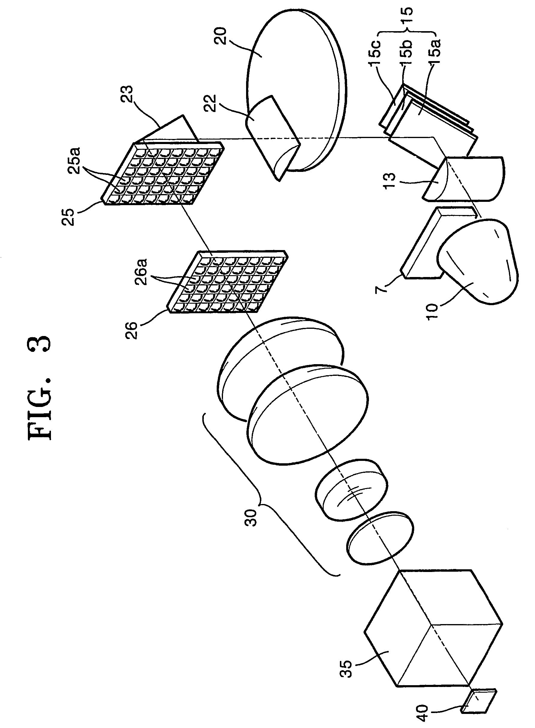
[0070]Referring to FIG. 3, a projection system according to the present invention includes a light source 10, an optical splitter 15 splitting light emitted from the light source 10 into color light beams according to a wavelength, at least one scrolling unit 20 scrolling the color light beams split by the optical splitter 15, and a light valve 40 processing the color light beams scrolled by the scrolling unit 20 according to an image signal to form a color image.

[0071]At least one fly eye lens (e.g., first and second fly eye lenses 25 and 26) and a group of lenses 30 may be further installed in an optical path between the scrolling unit 20 and the light valve 40. The color image formed by the light valve 40 is magnified and projected onto a screen by a projection lens system (not shown).

[0072]Referring to FIGS. 4A and 4B, the light source 10 emits white light and is a lamp light source in which light (radial light or arc light) emitted from a bulb 3 having discharging tips 1 is ref...

second embodiment

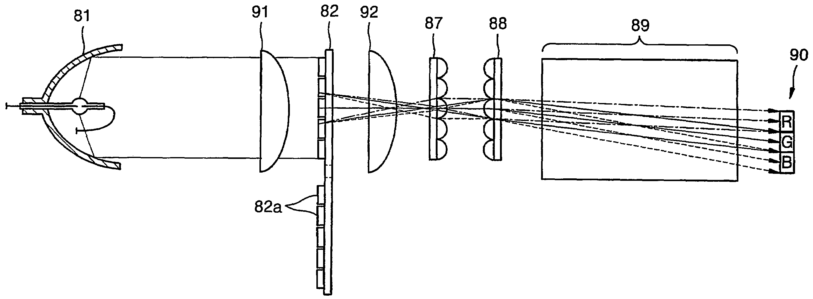
[0107]Referring to FIG. 9, a projection system according to the present invention includes a light source 50, an optical splitter 55 splitting light emitted from the light source 50 into color light beams according to a wavelength, at least one scrolling unit 60 scrolling the color light beams split by the optical splitter 55, and a light valve 67 processing the color light beams scrolled by the scrolling unit 60 according to an image signal to form a color image. The color image formed by the light valve 67 is magnified and projected onto a screen 70 by a projection lens system 68.

[0108]The light source 50 emits white light and includes a lamp 51 which generates light and a reflection mirror 53 which reflects light emitted from the lamp 51 and guides the path of the reflected light. The reflection mirror 53 may be an elliptic mirror whose first focal point f1 is the position of the lamp 51 and a second focal point f2 is a point where light is focused. Alternatively, the reflection ...

third embodiment

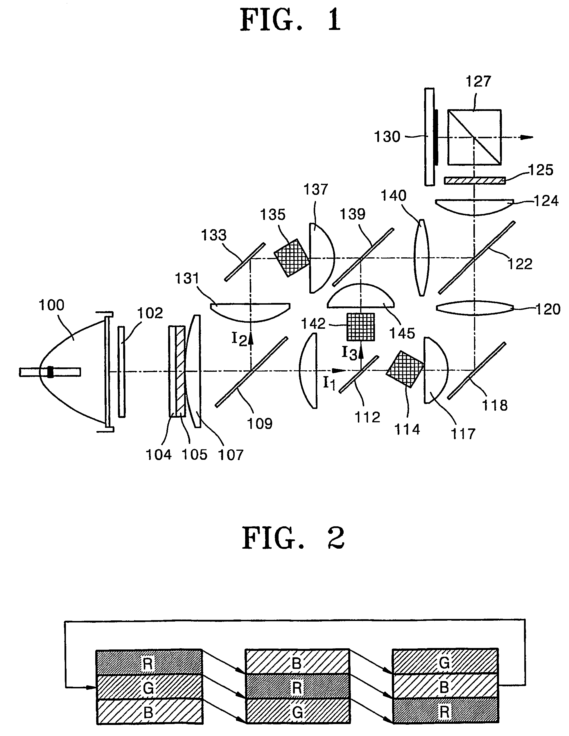
[0128]Referring to FIG. 12, the projection system according to the present invention includes a light source 70, a scrolling unit 73, an optical splitter 75 for splitting the light passed through the scrolling unit 73 according to a color, a color bar forming unit for making color beams split by the optical splitter 75 be overlapped a color beam by another beam of the same color, and a light valve 80 for forming a color image by turning on / off individual pixels according to a received image signal. The scrolling unit 73 is installed before the optical splitter 75, and a prism 74 is further provided between the scrolling unit 73 and the optical splitter 75. If the light source 70 is an elliptic mirror, preferably, a collimating lens 72 is further provided between the light source 70 and the scrolling unit 73.

[0129]Light beams emitted from the light source 70 is transmitted by the scrolling unit 73 and is then made incident upon the optical splitter 75 via the prism 74. Since the scro...


PUM


Abstract

A highly efficient lighting system, a scrolling unit, and a projection system adopting the highly efficient lighting system and the scrolling unit are provided. The scrolling unit has at least one lens cell. From the viewpoint of light incident upon the at least one lens cell, the rotation of the at least one lens cell is converted into a rectilinear motion of a lens array, such that incident light is scrolled. The projection system includes a light source, an optical splitter, at least one scrolling unit, and a light valve. The optical splitter splits light emitted from the light source according to wavelength. The at least one scrolling unit has at least one lens cell. The lens cell has an incident side and an emitting side and divides incident light into light beams. The rotation of the lens cell causes a rectilinear motion of the light beams, thereby scrolling incident light. The light emitted from the light source is separated into color beams by the optical splitter and the scrolling unit, and the color beams are focused on the light valve. The light valve processes incident light according to an input image signal in order to form a color image.

Description

TECHNICAL FIELD[0001]The present invention relates to a highly efficient lighting system, a scrolling unit for scrolling incident light, and a projection system employing the highly efficient lighting system and the scrolling unit, and more particularly, to a highly efficient lighting system which increases a light efficiency and reduces etendue of a light source to be made compact in a single-panel structure, a scrolling unit which performs scrolling in an improved way, and a projection system employing the highly efficient lighting system and the scrolling unit.BACKGROUND ART[0002]Projection systems are classified into three-panel projection systems and single panel projection systems according to the number of light valves which form an image by controlling the on / off operation of light emitted from a high power lamp used as a light source on a pixel-by-pixel basis. The single panel projection system may have an optical system smaller than that of the three-panel projection syste...

Claims


Application Information

Patent Timeline
Patent Type & Authority Patents(United States)
IPC IPC(8): G03B21/14F21V7/00F21V11/08F21V11/16G02B3/06G02B26/08G02B27/00G02B27/14G03B21/00H04N9/31
CPCG02B3/06G02B26/0875G02B27/1033H04N9/3197G02B27/1086G02B27/148G03B21/00G03B21/14H04N9/3117H04N9/3152G02B27/1053F21V7/0025F21V11/08F21V11/16G03B21/2066G03B21/208G03B21/005
Inventor KIM, DAE-SIKPARK, YUNG-JUNCHO, KUN-HOLEE, HEE-JOONGCHUNG, CHONG-SAMCHOI, JONG-CHULKIM, TAE-HEE
Owner SAMSUNG ELECTRONICS CO LTD
Why Eureka
Try Eureka