Laser projection illumination system

a laser projection and illumination system technology, applied in the direction of picture reproducers, picture reproducers using projection devices, instruments, etc., can solve the problems of reducing the efficiency of any use of diffusive-based de-speckling techniques, increasing cost and complexity, and undesirable light loss associated with fiber coupling techniques, so as to reduce speckling, reduce cost and complexity, and provide high-power cluster beams

Active Publication Date: 2021-07-20
BARCO NV
View PDF19 Cites 1 Cited by
  • Summary
  • Abstract
  • Description
  • Claims
  • Application Information

AI Technical Summary

Benefits of technology

[0014]It is an advantage of the invention that it efficiently provides a high power cluster beam with a limited etendue and with reduced speckling.
[0015]In an embodiment of the light beam projection arrangement according to the present invention, the clusters of light sources are arranged so that their respective clusters of light beams pass a light deviation system, which changes the direction of one or several individual light beams so that the individual light beams becomes positioned closer to each other and the etendue of the corresponding cluster of light beams is reduced.
[0016]The embodiment is based on the inventive insight of the inventors that individual light beams can advantageously be manipulated to improve the etendue of the cluster light beams.
[0017]In a particular embodiment, the light deviation system comprises a mirror system, the mirror system having a mirror substrate with a coating deposited on selected areas thereof, such that the mirror changes the direction of a selection of the individual light beams.
[0018]It is an advantage of this embodiment that it efficiently changes the direction of individual light beams and combines them.
[0019]In an embodiment of the light beam projection arrangement according to the present invention, the light sources are arranged so that their corresponding light beams pass a beam expander.

Problems solved by technology

Further, a large spread of the angular and spatial distribution between the primary colors will reduce the efficiency of any use of diffusive-based de-speckling techniques later in the system.
However there are undesirable light losses associated with the fiber coupling technique.
Further, fiber based solutions needs fiber optics for every laser which increases cost and complexity.
U.S. Pat. No. 8,066,389 discloses a beam alignment chamber for reducing the etendue, but it does not teach how to match the etendues of the several cluster light beams that are to be combined in a combiner rod and / or blended.

Method used


Image

  • Laser projection illumination system
  • Laser projection illumination system
  • Laser projection illumination system

Examples


Embodiment Construction

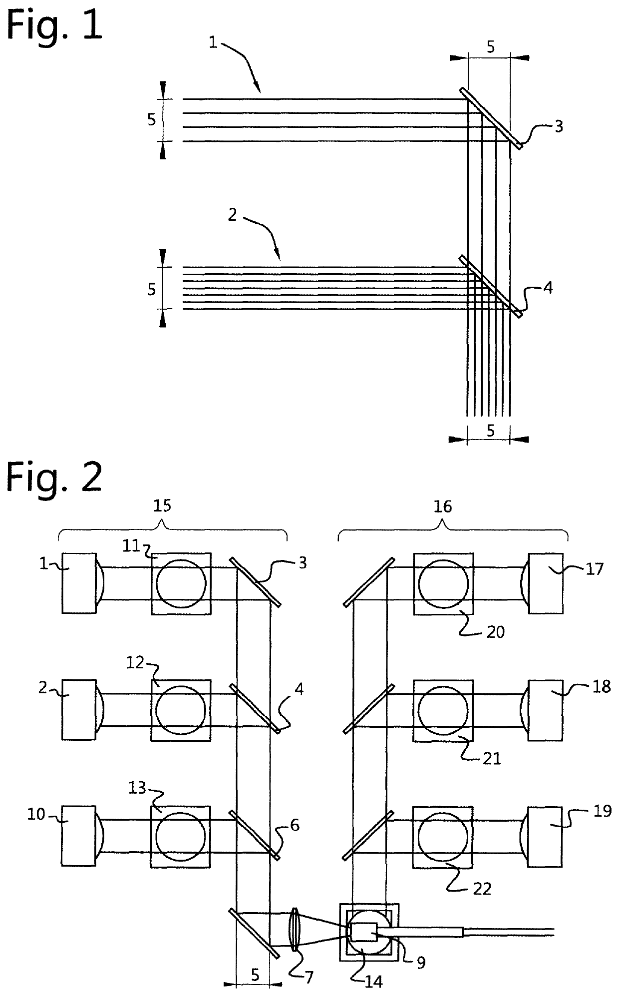
[0056]FIG. 1 shows an example of an embodiment of the present invention with two cluster beams 1 and 2 and dichroic mirrors 3 and 4 to alter the direction of the light beams. The three-dimensional nature of light beams makes the number of visible beams in a two dimensional snapshot like FIG. 1 to depend on the beam distribution and the angle of the two-dimensional view. The etendue of an individual beam of cluster 1 may be different than the etendue of an individual beam of set 2. It is however crucial that the etendues of the cluster beams 1 and 2 are equal as well as the etendue of the final beam leaving mirror 4. The two-dimensional projection of this etendue is indicated in FIG. 1 by 5.

[0057]FIG. 2 shows an overview of an embodiment of the present invention.

[0058]Light beams 1 and 2 are here presented in a system configuration where 1 and 2 could for example be blue and green light. A third light beam 10 is added; this could for example be red light. 1, 2 and 10 contribute to th...


PUM


Abstract

A light beam projecting arrangement including a first cluster of light sources arranged to provide a first cluster of light beams having a first etendue and a second cluster of light sources arranged to provide a second cluster of light beams having a second etendue, and means for changing the direction of the first cluster and / or the second cluster of light beams. The light sources are arranged so that the total etendue of the first cluster of light beams is substantially equal to the etendue of the second cluster of light beams; and where the means for changing the direction are arranged so that the clusters of light beams are brought into a combined cluster light beam having substantially the same etendue as the larger one of the first etendue and the second etendue.

Description

[0001]The present invention relates to a projection illumination system and to a method of operating or manufacturing a projection illumination system.BACKGROUND[0002]Laser based projection systems are considered to be a promising technology for (high-end) projection due to their high lifetime, saturated colors, stable light output, etc. Two focus areas in this field are how to increase the efficiency and how to deal with the speckle phenomenon. For example, international patent application publication WO2012 / 139634 A1, in the name of the present applicant, describes how to decrease the impact of the speckle behaviour by using an increased diffusing power.[0003]Laser based projection systems involve distinct red, green and blue light sources that can provide primary light beams or primary colors. A primary cluster light beam can comprise a plurality of individual light beams. There is an angular and spatial distribution associated with a cluster light beam. The angular distribution ...

Claims


Application Information

Patent Timeline
Patent Type & Authority Patents(United States)
IPC IPC(8): G03B33/12G02B27/48G03B21/20G02B27/28G02B27/14G02B27/09H04N9/31
CPCG03B33/12G02B27/0905G02B27/0922G02B27/14G02B27/283G02B27/48G03B21/208G03B21/2013G03B21/2033G03B21/2066G03B21/2073H04N9/3161
Inventor D'OOSTERLINCK, WOUTERJANSSENS, PETERCOULIER, NICO
Owner BARCO NV
Why Eureka
Try Eureka