Exposure apparatus with efficient uniform light output

a technology of uniform light output and illumination apparatus, applied in the field of illumination apparatus, can solve the problems of reducing illumination efficiency, difficult for all light source images to enter the lens cell, and ineffective utilization of the entire light emitted from the lamp, so as to improve illumination efficiency and illumination uniformity

Active Publication Date: 2006-10-17
ADTEC ENG +1
View PDF3 Cites 0 Cited by
  • Summary
  • Abstract
  • Description
  • Claims
  • Application Information

AI Technical Summary

Benefits of technology

[0012]The present inventors noted that a light source which has a light-emitting portion substantially similar to the configuration of lens cells of a fly-eye lens (the configuration of the light-emitting portion of a rod), i.e., the contour configuration of an exit surface of an optical integrator can guide most of light emitted from the light-emitting portion to an illumination area and improve illumination ef

Problems solved by technology

In actuality, in the case that Etendue is large and the configuration of the light-emitting portion is different from the configuration of an area illuminated by the light reaching a two-dimensional SLM as in the case of a lamp, entire light emitted from the lamp cannot be effectively utilized, resulting in a decreased illumination efficiency.
Actually, however, it is diff

Method used


Image

  • Exposure apparatus with efficient uniform light output
  • Exposure apparatus with efficient uniform light output
  • Exposure apparatus with efficient uniform light output

Examples


examples

[0064]A description will be given by tanking the case of using a DMD as the two-dimensional SLM 186 as an example. As illustrated in FIGS. 9A and 9B, a DMD 200 serving as the two-dimensional SLM is provided for each of the exposure heads 16611 to 166mn. The DMD 200 modulates an incident light beam in accordance with image data on a pixel-by-pixel basis.

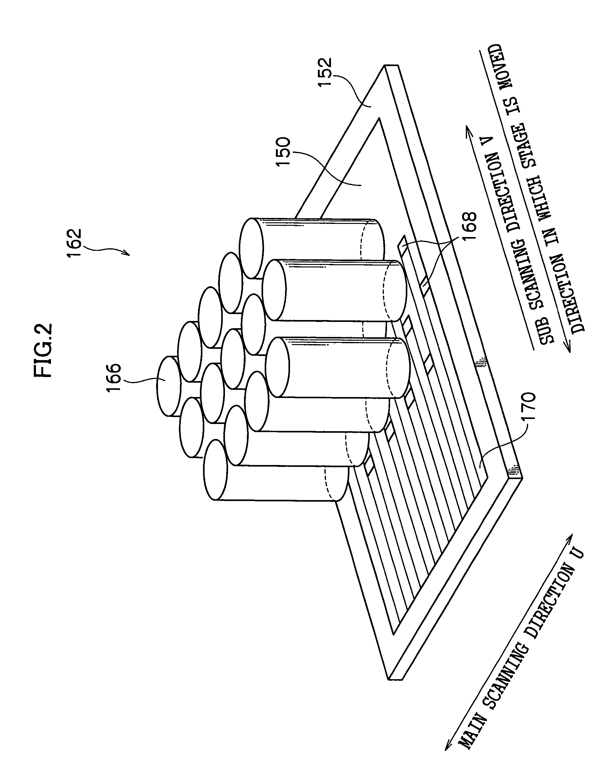
[0065]FIG. 9A illustrates scanning loci of real images (beam spots BS) of pixel portions in the case in which the DMD 200 is not tilted with respect to a main scanning direction U. FIG. 9B illustrates scanning loci of beam spots BS in the case in which the DMD 200 is tilted with respect to the main scanning direction U. The DMD 200 is preferably arranged so as to be tilted a little so that a predetermined angle θ (e.g., 0.1° to 1°) is formed by a direction of its side and the main scanning direction U.

[0066]In the DMD 200, a large number of (e.g., 600) pixel columns, in each of which a large number of (e.g., 800) pixel portions are ar...


PUM


Abstract

An object of the present invention is to provide an exposure apparatus which is capable of obtaining high illumination efficiency and performing uniform exposure. In accordance with the exposure apparatus that includes a light source, an optical integrator to which light is supplied from the light source and a two-dimensional spatial light modulator illuminated by light which has transmitted the optical integrator, an optical fiber bundle end portion for emitting light to the optical integrator is provided in the light source, and the light-emitting area of the optical fiber bundle end portion is, as seen from the light-emitting side, substantially similar to the contour configuration of light-emitting surface of the optical integrator. Thus, most of the light emitted from the optical fiber bundle end portion can be illuminated onto a set illumination area. As a result, high illumination efficiency can be obtained and uniform exposure can be realized.

Description

CROSS-REFERENCE TO RELATED APPLICATION[0001]This application claims priority under 35 USC 119 from Japanese Patent Application, No. 2003-14477, the disclosure of which is incorporated by reference herein.BACKGROUND OF THE INVENTION[0002]1. Field of the Invention[0003]The present invention relates to an exposure apparatus, and in particular to an exposure apparatus which is capable of improving illumination efficiency and performing uniform exposure.[0004]2. Description of the Related Art[0005]An exposure apparatus is known, which has an illumination optical system for illuminating a two-dimensional spatial light modulator (which hereinafter is referred to as a two-dimensional SLM) such as an LCD (liquid crystal display) or a DMD (digital micromirror device; trademark) with light from a light source, and which exposes an optical image controlled by the two-dimensional SLM onto a photosensitive material. The two-dimensional SLM must be uniformly illuminated in such an exposure apparat...

Claims


Application Information

Patent Timeline
IPC IPC(8): G01B11/02G02B26/08B41J2/46G02B6/00G02B6/06G02B27/00G03F7/20H01L21/027H04N5/74
CPCB41J2/46G02B27/0927G02B27/0994G02B27/0961G02B6/06H04N5/7458G02B2006/0098G03F7/20
Inventor OMORI, TOSHIHIKO
Owner ADTEC ENG
Why Eureka
Try Eureka