Light source and display system

a light source and display system technology, applied in the field of solid-state lighting, can solve the problems of limited brightness and inability to generate high-brightness ligh

Active Publication Date: 2020-03-10
APPOTRONICS CORP LTD
View PDF20 Cites 0 Cited by
  • Summary
  • Abstract
  • Description
  • Claims
  • Application Information

AI Technical Summary

Benefits of technology

[0013]From the technical method mentioned above it is can be known that compared with conventional technology, the light source of the present invention can combine the light beam output from another lighting device whose spectrum has a large overlap with the spectrum of any lighting device in the original light emitting device group. Moreover, because the etendue of the light beam finally output from the original light emitting device group is equal to the etendue of one of the lighting devices of the group, and the etendue of the light beam finally output from the supplementary light emitting device group is equal to the etendue of one of the lighting devices of the group, so the total etendue after the geometric-based light combination is equal to the sum of the etendue of one lighting device in the original light emitting device group and one lighting device in the supplementary light emitting device group. Compared with the conventional technology, the method of the present invention can reduce the etendue of the entire light source and increase the brightness of the light source while combining the light beam of another lighting device whose spectrum has a large overlap with the spectrum of any lighting device in the original light emitting device group.

Problems solved by technology

According to etendue conservation principle, the smaller the etendue of the light source, the higher the brightness, so the LED light source in this existing technology cannot generate high brightness light while achieving RGBW color illumination.
Therefore it is still limited in terms of brightness.

Method used


Image

  • Light source and display system
  • Light source and display system
  • Light source and display system

Examples


embodiment one

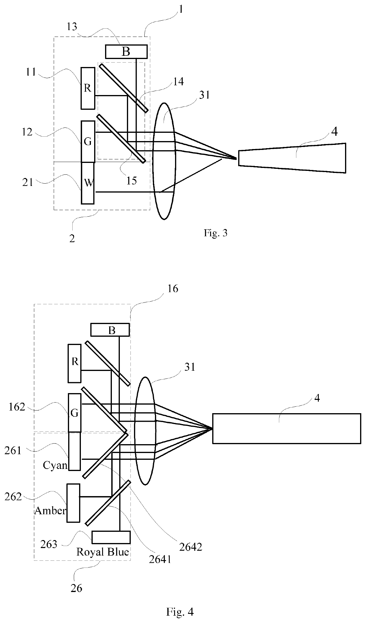
[0047]FIG. 3 illustrates an embodiment of the light source of the present invention. In the present embodiment, the light beams from the original light emitting device group and the supplementary light emitting device group are finally output on different cross sections of the geometric-based light combining device. For easier explanation, in the following text words ‘upper, ‘lower are used to describe the spatial relationship of the various elements, and refer to upper side and lower side in the Figure respectively.

[0048]Refer to FIG. 3, in the present embodiment, in particular the original light emitting device group including three primary color LED is used as an example for explanation. Specifically the original light emitting device group 1 includes a red LED 11 (labeled in the Figure as R), a green LED 12 (labeled in the Figure as G) and a blue LED 13 (labeled in the Figure as B). People skilled in the art should know that in fact there is no limit to the amount of the LED use...

embodiment two

[0060]FIG. 4 illustrates an alternative embodiment of the light source. The light beams finally output from an original light emitting device group and a supplementary light emitting device group are still not on a same cross section of a geometric-based light combining device. But in the embodiment described above the supplementary light emitting device group consists of a white LED; in fact to achieve the goal of supplementary lighting, the supplementary light emitting device group can consists of multiple LED whose spectra have large overlaps with any LED in the original light emitting device group.

[0061]As shown in FIG. 4, the supplementary light emitting device group 26 includes, for example, a cyan LED 261 (labeled in the Figure as Cyan), an amber LED 262 (labeled in the Figure as Amber), a royal blue LED 263 (labeled in the Figure as Royal Blue). The three light beams output from the cyan LED 261, the amber LED 262 and the royal blue LED 263 are combined by a wavelength-based...

embodiment three

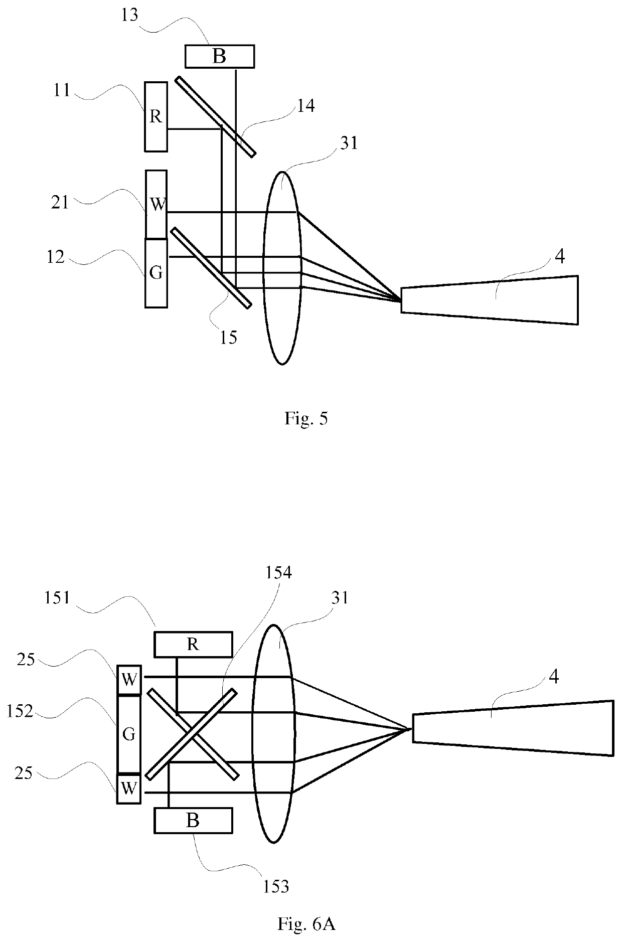
[0068]In embodiment one and embodiment two described above, the supplementary light emitting device group is entirely located below the original light emitting device group; of course the supplementary light emitting device group can also be entirely located above the original light emitting device group. In fact, the supplementary light emitting device group can also be located between two LED of the original light emitting device group, such as in an alternative embodiment of the light source of the present invention shown in FIG. 5.

[0069]A difference between the light source of the present embodiment and the light source of embodiment one is that the white LED 21 which plays the role of the supplementary light emitting device group is located between the red LED 11 and the green LED 12 of the original light emitting device group.

[0070]The inner structure of the original light emitting device group, and the location relationship of the LED and the two dichroic mirrors in the origi...


PUM

PropertyMeasurementUnit
tilted angleaaaaaaaaaa
wavelengthaaaaaaaaaa

Abstract

Disclosed are a light source and a display system. The light source comprises at least one original light emitting device group (1) and at least one supplementary light emitting device group (2). The original light emitting device group (1) comprises at least two LED (11, 12, 13) and a wavelength light combining device (14, 15), wherein the energy of the overlapped spectrum in the normalized spectrum of the two LED is smaller than 50% of the smaller energy of the two, and the wavelength light combining device combines the light output from all the LED in the original light emitting device group (1) in a wavelength light combining way. The supplementary light emitting device group (2) comprises at least one LED (21). The energy of the overlapped spectrum in the normalized spectrum of any LED of the supplementary light emitting device group (2) and at least one LED of the original light emitting device group (1) is larger than or equal to 10% of the smaller energy of the two. The light source also comprises a geometric light combining device (31), which combines the light finally output from the original light emitting device group (1) and the light finally output from the supplementary light emitting device group (2) into one beam of light in a geometric light combining way.

Description

FIELD OF THE INVENTION[0001]This invention relates to solid state lighting, and in particular, it relates to a light source and a display system.DESCRIPTION OF THE RELATED ART[0002]A solid state lighting device, including LED (Light Emitting Diode) and LD (Laser Diode), is a solid state semiconductor device which can directly convert electrical power into visible light.[0003]The LED and phosphor-covered LED (PC-LED) are suitable in general lighting as lighting sources. The working mechanism of a phosphor-covered LED is to coat phosphor onto the surface of LED chip in order to emit fluorescent light from the phosphor which is excited by the LED light. The most common example of phosphor-covered LED is to coat yellow phosphor onto the surface of blue LED to emit white light which is a combination of the yellow light generated by the yellow phosphor excited by the blue light emitted from the blue LED and remaining blue light which is not absorbed. Moreover, there is LED product on the ...

Claims


Application Information

Patent Timeline
Patent Type & Authority Patents(United States)
IPC IPC(8): G02B27/14G02B27/10G02B27/09F21V9/20
CPCG02B27/1006G02B27/146G02B27/141G02B27/102G02B27/145G02B27/0994F21V9/20
Inventor YANG, YIHU, FEI
Owner APPOTRONICS CORP LTD
Why Eureka
Try Eureka