Force-driven socket for light bulb

a technology for sockets and light bulbs, applied in the field of sockets, can solve the problems of excessive time involved, time consumption, and energy consumption, and achieve the effect of reducing the amount of energy consumed and consuming tim

Active Publication Date: 2020-10-06
WINTERGREEN CORP
View PDF98 Cites 1 Cited by
  • Summary
  • Abstract
  • Description
  • Claims
  • Application Information

AI Technical Summary

Benefits of technology

[0005]It is, therefore, advantageous for a socket to receive a threaded bulb without requiring the labor-intensive step of threading the individual bulb into the socket. It is also advantageous to enable quick withdrawal of the bulb such as for replacement of the bulb or disassembly of the installation. It is beneficial to also provide a socket which is configured to operatively receive either a threaded light bulb or a bayonet light bulb, interchangeably.

Problems solved by technology

Installation and removal of a conventional threaded light bulb into a conventional threaded socket, although well accepted for achieving electrical connectivity, is time consuming.
The time involved and energy expended becomes excessive when considering installations involving numerous light bulbs, such as string lights and commercial lighting installations.

Method used


Image

  • Force-driven socket for light bulb
  • Force-driven socket for light bulb
  • Force-driven socket for light bulb

Examples


Embodiment Construction

[0017]The present invention will now be described in detail hereinafter by reference to the accompanying drawings. The invention is not intended to be limited to the embodiments described; rather, this detailed description is provided to enable any person skilled in the art to make and practice the invention.

[0018]As used herein, the terms “proximal” and “distal” (excluding horizontal cross-sections) are used to refer to the axial ends of the socket and various components. The term “proximal end” refers to the end closely adjacent the socket opening for receipt of the bulb and the term “distal end” refers to the end of the socket for connecting to a wire. Also, as used herein, the “axial direction” refers to the longitudinal axis of the socket, along the center thereof. The term “transverse” direction refers to a direction which intersects the longitudinal axis, at any angle.

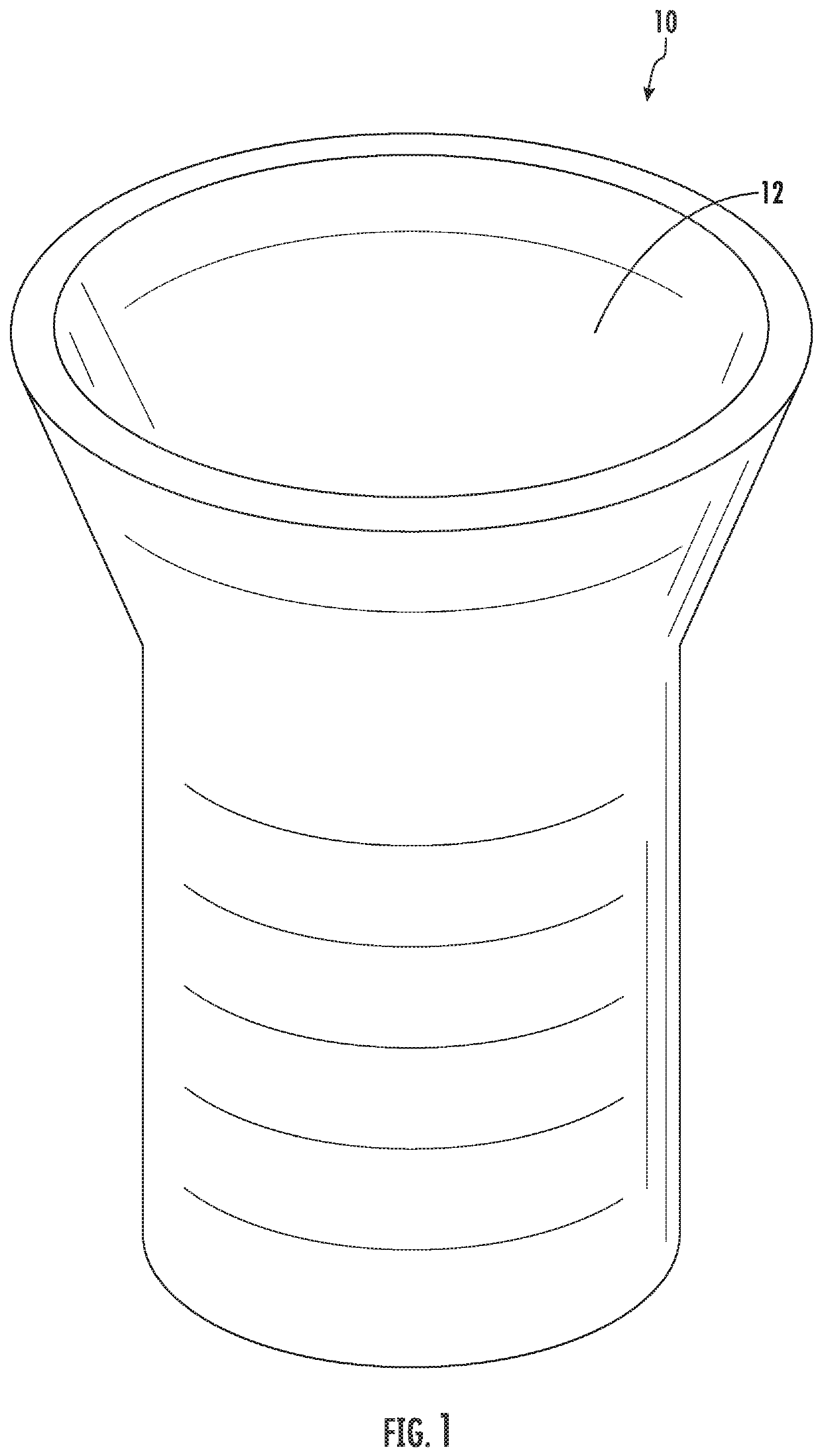
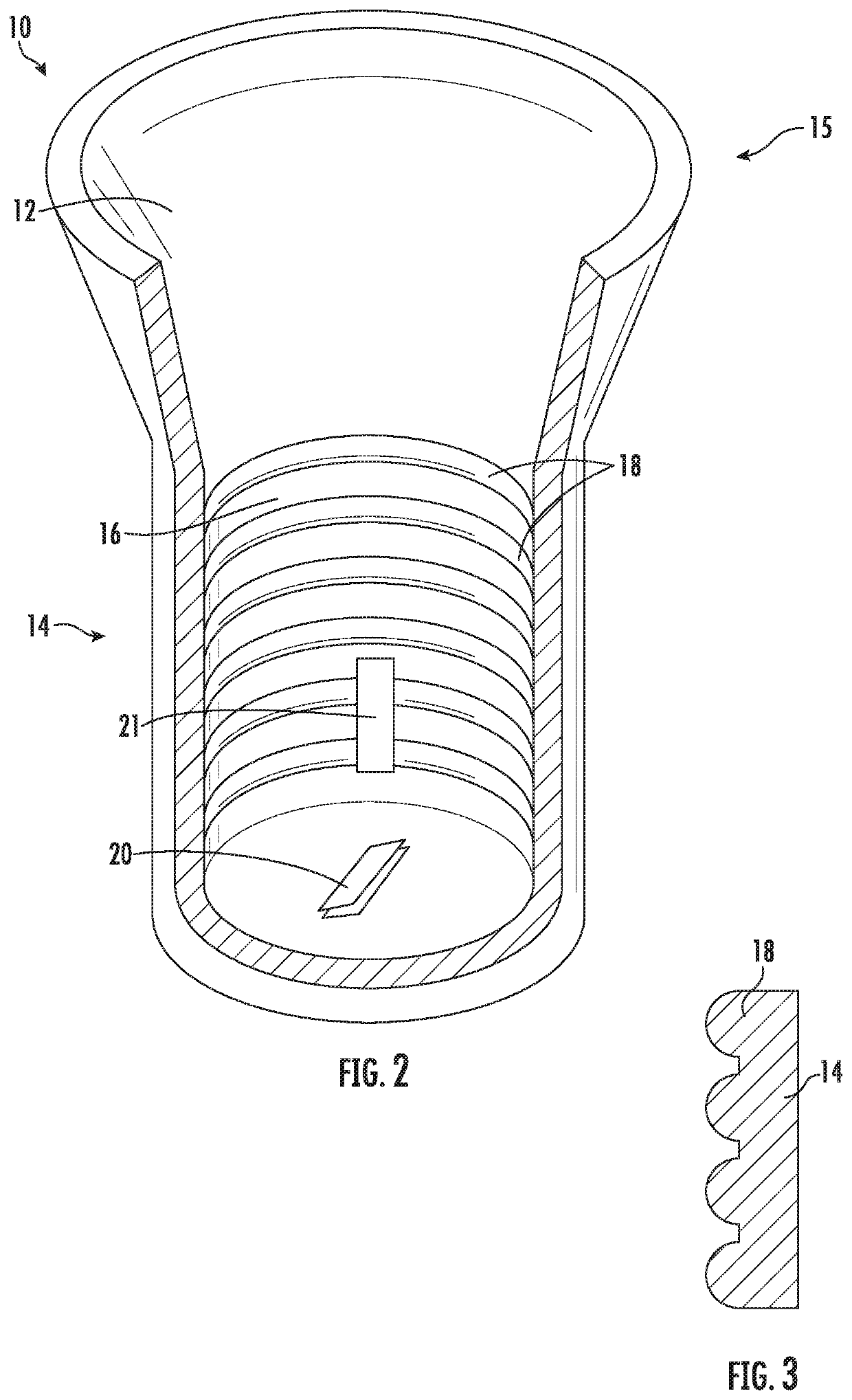
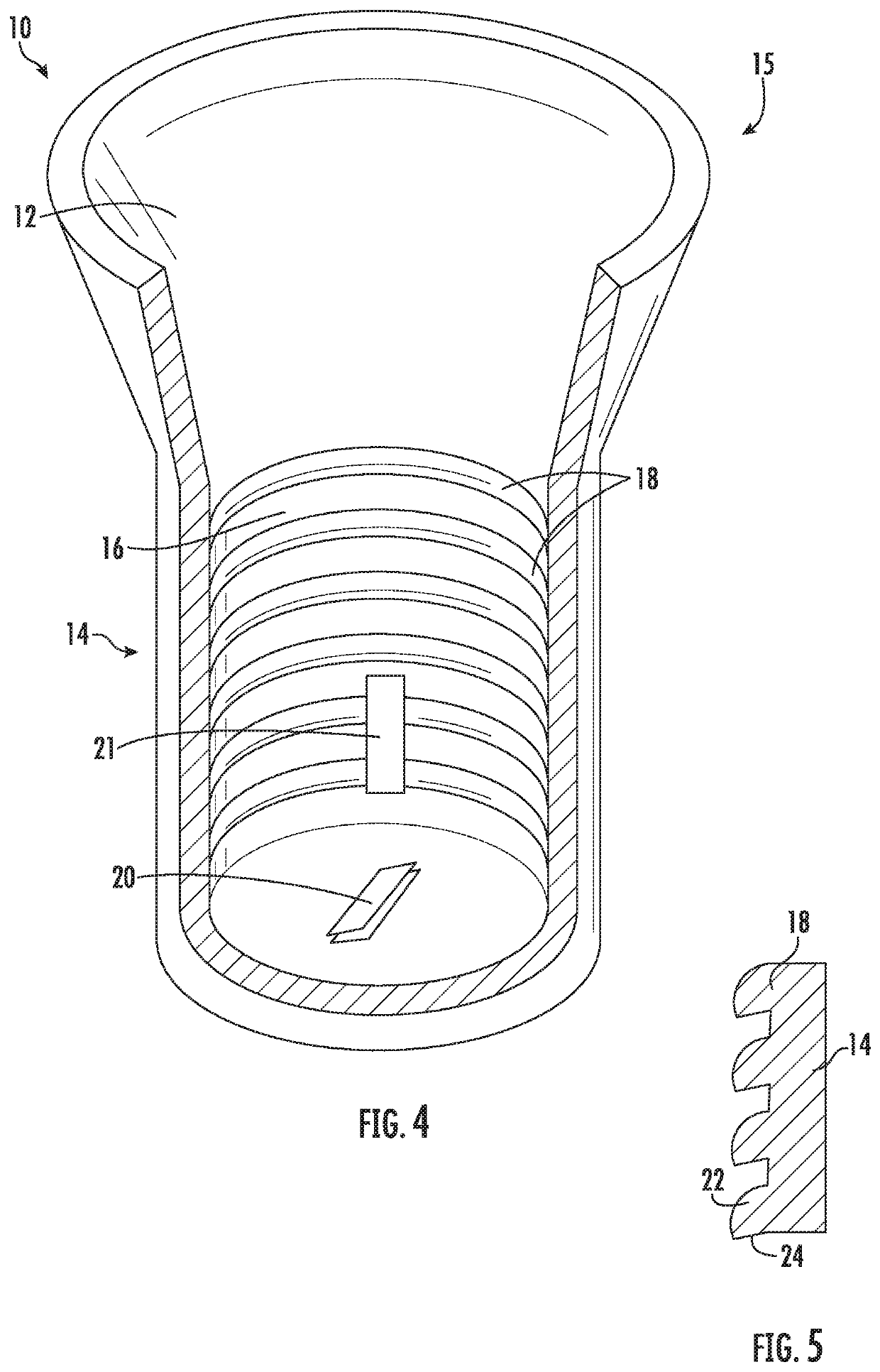
[0019]As shown in FIGS. 1-3, the socket 10 is generally cylindrical with a hollow, bulb receiving cavity 12 d...


PUM


Abstract

A socket for allowing a threaded light bulb or a bayonet light bulb to be quickly and effectively inserted into and removed from the socket by axial force, avoiding the need for it to threaded by rotational forces within the socket to achieve connectivity. The socket includes a bulb interface including a plurality of flanges for cooperating with a bulb having a threaded base and / or a bayonet base.

Description

CROSS REFERENCE TO RELATED APPLICATIONS[0001]This application claims the benefit of Provisional Patent Application Nos. 62 / 573,212, filed Oct. 17, 2017, and 62 / 531,973, filed Jul. 13, 2017, the disclosures of which are hereby incorporated by reference.FIELD OF THE INVENTION[0002]The present invention is directed to a socket for allowing a threaded light bulb or a bayonet light bulb to be quickly and effectively inserted into the socket by axial force, avoiding the need for it to be threaded by rotational forces within the socket to achieve connectivity.BACKGROUND OF THE INVENTION[0003]Installation and removal of a conventional threaded light bulb into a conventional threaded socket, although well accepted for achieving electrical connectivity, is time consuming. The time involved and energy expended becomes excessive when considering installations involving numerous light bulbs, such as string lights and commercial lighting installations. A socket is intended to secure a light bulb ...

Claims


Application Information

Patent Timeline
Patent Type & Authority Patents(United States)
IPC IPC(8): F21V21/002H01R33/46H01R33/22H01R33/90F21V19/00
CPCH01R33/90H01R33/22H01R33/46F21V19/006F21V21/002
Inventor HALE, WILLIAM
Owner WINTERGREEN CORP
Why Eureka
Try Eureka