Novel liquid filling device

A technology for filling equipment and liquids. It is used in liquid distribution, transportation or transfer devices, special distribution devices, packaging, etc. It can solve the problems that affect the stable operation of the equipment, easily mix with gas, and simplify the pipeline layout. , The effect of reducing the amount of dissolved gas and reducing the workload

Active Publication Date: 2020-10-16
HENAN AEROSPACE HYDRAULIC & PNEUMATIC TECH
View PDF8 Cites 1 Cited by
  • Summary
  • Abstract
  • Description
  • Claims
  • Application Information

AI Technical Summary

Problems solved by technology

[0004] The purpose of the present invention is to provide a new type of liquid filling equipment, which is used to solve the technical problem that the current liquid filling equipment is easily mixed with gas during the filling process, resulting in more mixed gas and affecting the stable operation of the equipment.

Method used


Image

  • Novel liquid filling device

Examples


specific Embodiment 1

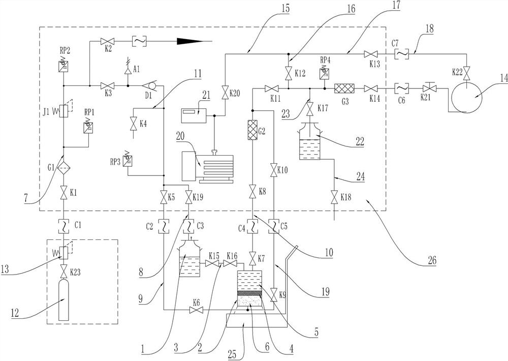
[0040] like figure 1 As shown, the new liquid filling equipment includes a liquid storage tank 1 and a squeeze tank 2. The liquid storage tank 1 and the squeeze tank 2 are connected through the liquid tank connecting pipeline 3, and the liquid tank connecting pipeline 3 is provided with a liquid inlet cut-off valve. , The liquid inlet cut-off valve is arranged between the liquid storage tank 1 and the squeeze tank 2 to control the on-off of the passage between the two. The liquid storage tank 1 is connected with an air filling pipeline. When injecting liquid into the squeeze tank 2, the liquid in the liquid storage tank 1 is pressed out by adding air and pressurizing the liquid storage tank 1. After the liquid injection is completed, close the inlet. Liquid shut-off valve. In this embodiment, there are two cut-off valves for liquid inlet, namely, the cut-off valve for liquid inlet K15 and the cut-off valve for liquid inlet K16. The two cut-off valves for liquid inlet can ensu...

specific Embodiment 2

[0086] The specific embodiment 2 of the novel liquid filling device of the present invention, the difference between the structure of the novel liquid filling device in this embodiment and the above specific embodiment 1 is that in this embodiment, when the piston is squeezed, it is directly injected into the extrusion chamber Gas, without vacuuming, at this time there is no need to set up a vacuuming pipeline for the extrusion chamber.

[0087] The specific embodiment 3 of the new liquid filling equipment of the present invention, the structure of the new liquid filling equipment in this embodiment differs from the above specific embodiment 1 only in that the vacuuming pipeline of the extrusion chamber is directly connected with the vacuum pump group.

[0088] Specific embodiment 4 of the novel liquid filling device of the present invention. The difference between the structure of the novel liquid filling device in this embodiment and the above specific embodiment 1 is that a ...

specific Embodiment 5

[0089] Embodiment 5 of the novel liquid filling equipment of the present invention. The structure of the novel liquid filling equipment in this embodiment differs from that of the above specific embodiment 1 only in that the electronic scale is set on the filling vehicle. In other embodiments, all pipelines can be arranged on the filling vehicle.


PUM


Abstract

The invention relates to a novel liquid filling device. The novel liquid filling device comprises a liquid storage container and an extrusion container internally provided with a piston, the piston divides an inner cavity of the extrusion container into a liquid injection cavity and an extrusion cavity, the liquid injection cavity is used for communicating with the liquid storage container, the extrusion cavity is used for allowing an extrusion power medium to enter to exert pressure on the piston so as to extrude a liquid within the liquid injection cavity, the piston is assembled in the extrusion container in a sliding sealing mode, a liquid injection pipeline is connected to the liquid injection cavity, and a liquid injection vacuumizing pipeline is used for vacuumizing the liquid injection pipeline, the liquid injection cavity and a cavity to be injected with the liquid. The novel liquid filling device is provided with the extrusion container, the liquid can be injected into the extrusion container through the liquid storage container, the piston is arranged in the extrusion container, the piston is pressed to extrude the liquid injection cavity, so that the condition that airis dissolved in the liquid due to the air directly extrudes the liquid is avoided, and the technical problem that during filling of an existing liquid filling device, air is prone to mix, and much mixed air is caused is solved.

Description

technical field [0001] The invention relates to a novel liquid filling device. Background technique [0002] The Chinese patent application with the application publication number CN109708896A and the application publication date of 2019.05.03 discloses a quantitative filling device for an attitude control power system. The filling device includes a filling console, a vacuum system, a filling container, an electronic scale, a stable The pressure system and the filling pipeline are used to supply the propellant from the filling container to the storage tank of the attitude control power system. The filling device places the pressure stabilizing system and the filling container together on the electronic scale, and the pressurized gas enters the filling container from the pressurized gas cylinder, which will not affect the filling accuracy. Before filling, connect the drain valve through the filling connection device to discharge and fill the propellant of the filling pipelin...

Claims


Application Information

Patent Timeline
Patent Type & Authority Applications(China)
IPC IPC(8): B67D7/02B67D7/06B67D7/40B67D7/78
CPCB67D7/0227B67D7/0277B67D7/0288B67D7/06B67D7/40B67D7/78
Inventor 黄世朋毛利亚曹伟张凯王永胜孙亚飞郭克伟鲁小强李鹏飞王标
Owner HENAN AEROSPACE HYDRAULIC & PNEUMATIC TECH
Why Eureka
Try Eureka