Method and device for detecting at least one object in the area between a primary coil and a secondary coil of an inductive charging device

a charging device and object detection technology, applied in the direction of instruments, using reradiation, transportation and packaging, etc., can solve the problems of interference in signal reception, and achieve the effect of increasing the redundancy of the device and reliably determining a foreign obj

Active Publication Date: 2020-11-17
ROBERT BOSCH GMBH
View PDF36 Cites 0 Cited by
  • Summary
  • Abstract
  • Description
  • Claims
  • Application Information

AI Technical Summary

Benefits of technology

[0008]The method described offers a cost-efficient and easily implementable option for detecting foreign objects in an inductive charging device, in particular, in an interspace between the primary coil and the secondary coil.
[0017]It may be provided that each of the ultrasonic transmitters is configured to emit repeatedly a first and / or a second ultrasonic signal. Each ultrasonic receiver in this case is configured to receive at least one additional ultrasonic signal sequence, which follows chronologically the previously received ultrasonic signal sequence. The processing unit detects at least one object in the area between a primary coil and a secondary coil of an inductive charging device as a function of a comparison of successive ultrasonic signal sequences with the associated reference ultrasonic sequences to detect. This offers the possibility of ascertaining the chronological change of received signals and thus, for example, to be able to draw conclusions about the movement of a dynamic foreign object in the area between the primary coil and a secondary coil.

Problems solved by technology

In this case, it may also involve interferences in the signal reception such as, for example, noise signals.

Method used


Image

  • Method and device for detecting at least one object in the area between a primary coil and a secondary coil of an inductive charging device
  • Method and device for detecting at least one object in the area between a primary coil and a secondary coil of an inductive charging device
  • Method and device for detecting at least one object in the area between a primary coil and a secondary coil of an inductive charging device

Examples


Embodiment Construction

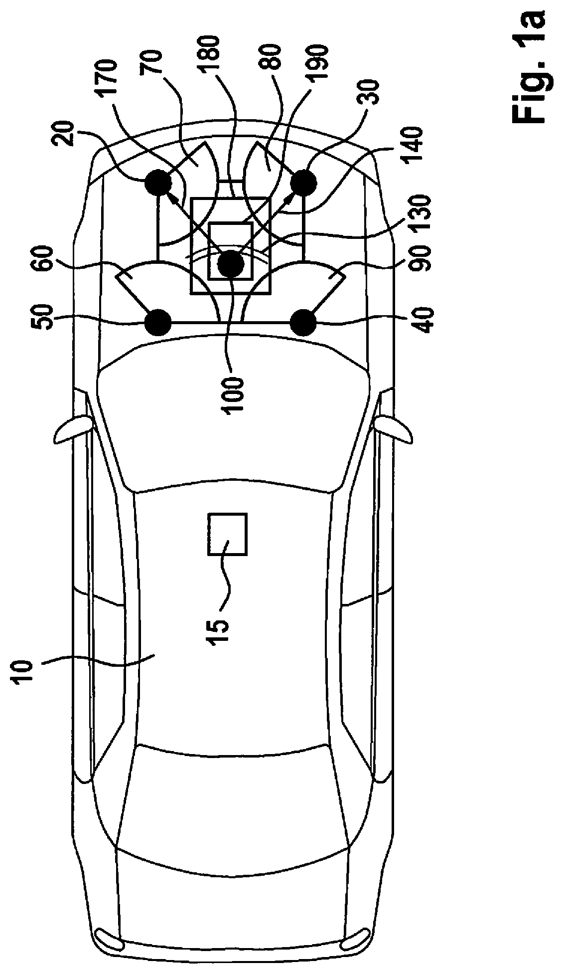
[0027]FIG. 1a shows a vehicle 10, which is positioned in such a way that primary coil 190 and secondary coil 180 are situated one above the other and an inductive energy transmission may be optimally carried out. A first ultrasonic transmitter 100, which emits a first ultrasonic signal 130 in the form of sound waves, is situated at a lateral edge of primary coil 190. A first ultrasonic receiver 20, a second ultrasonic receiver 30, a third ultrasonic receiver 40 and a fourth ultrasonic receiver 50 are situated at the underbody of vehicle 10 around secondary coil 180 of the inductive charging device in such a way that ultrasonic receivers 20, 30, 40, and 50 each form the corners of a square and the secondary coil is located centrally within this stretched square. First ultrasonic transmitter 100 transmits an ultrasonic signal 130 in the direction of first ultrasonic receiver 20 and of second ultrasonic receiver 30. First receiving area 70 of first ultrasonic receiver 20 and second rec...


PUM


Abstract

A method for detecting at least one object between primary and secondary coils of a vehicle's inductive-charging-device. A first ultrasonic signal (FUS) is emitted with a first ultrasonic-transmitter (UT) situated at the primary-coil. A FUS-sequence is received with a first ultrasonic-receiver (FUR) at the vehicle. The FUS-sequence includes at least one first direct-receive signal. Alternatively / in addition, the FUS sequence includes additional receive signals, each of which corresponds to an indirect transmission of the ultrasonic-signal from the at least one UT to the FUR. The first direct receive signal is ascertained within the FUS-sequence and / or additional receive signals are ascertained within the FUS-sequence. The first received ultrasonic-signal-sequence, which includes the ascertained direct-receive-signal and / or ascertained additional receive signals is compared to a first reference-ultrasonic-signal-sequence. At least one object is subsequently detected between the primary and secondary coils as a function of this comparison.

Description

FIELD OF THE INVENTION[0001]The present invention relates to a method and a device for detecting at least one object in the area between a primary coil and a secondary coil of an inductive charging device for a vehicle.BACKGROUND INFORMATION[0002]The document DE 10 2009 033 236 A1 discusses a device for inductively transmitting electrical energy from a stationary unit having at least one primary inductance to a vehicle adjacent to this stationary unit having at least one secondary inductance. The device includes a unit for detecting the presence of an object within a particular space. The detection unit includes a contactless sensor, for example, an ultrasonic sensor. In this case, for example, four ultrasonic sensors are provided, which are situated symmetrically in the shape of a square. The presence of the foreign body is deduced by evaluating the reflection back to the emitting sensor, by evaluating the reflection strength and by evaluating the chronological sequence of the meas...

Claims


Application Information

Patent Timeline
Patent Type & Authority Patents(United States)
IPC IPC(8): G01S15/04B60L53/124B60L53/126
CPCG01S15/04B60L53/126B60L53/124Y02T10/70Y02T10/7072Y02T90/14
Inventor SCHUMANN, MICHAEL
Owner ROBERT BOSCH GMBH
Why Eureka
Try Eureka