Liquid flow sensor with adjustable operational range

a liquid flow sensor and adjustable technology, applied in the direction of volume/mass flow by differential pressure, measurement devices, instruments, etc., to achieve the effect of increasing the speed of the liquid flowing

Active Publication Date: 2020-11-24
WILGER INDS
View PDF10 Cites 0 Cited by
  • Summary
  • Abstract
  • Description
  • Claims
  • Application Information

AI Technical Summary

Benefits of technology

[0009]The present disclosure provides a flow meter apparatus that uses a meter wheel rotated by the flowing liquid to measure the flow rate and that can accommodate a wide range of flows. In flow meters using a meter wheel, proper operation requires that the liquid contacting the wheel be travelling at a sufficient speed to turn the wheel at a sufficient speed to record accurately. In the present disclosure as the required flow rate, being the flow rate through the liquid conduit, reduces, the size of the orifice that the liquid flows through into the meter wheel housing is correspondingly reduced to thereby increase the speed of the liquid flowing therethrough to maintain the flow rate. By reducing the orifice size for lower flow rates a strong and consistent jet can be maintained against the wheel to record accurately. Each jet insert will accommodate a range of flow rates, and when the flow rate changes such that same is outside the range, then a different jet insert with a different sized orifice is inserted in the input port.

Problems solved by technology

A problem with these types of flow meters, however, is that they are accurate only within a range of a factor of about ten, in that they accurately measure flows from a minimum flow rate to a maximum flow rate that is about ten times the minimum flow rate.

Method used


Image

  • Liquid flow sensor with adjustable operational range
  • Liquid flow sensor with adjustable operational range
  • Liquid flow sensor with adjustable operational range

Examples


Embodiment Construction

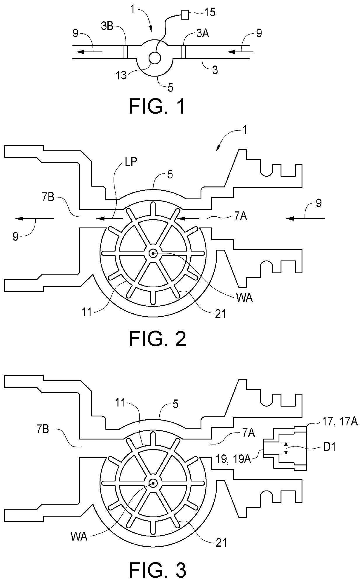
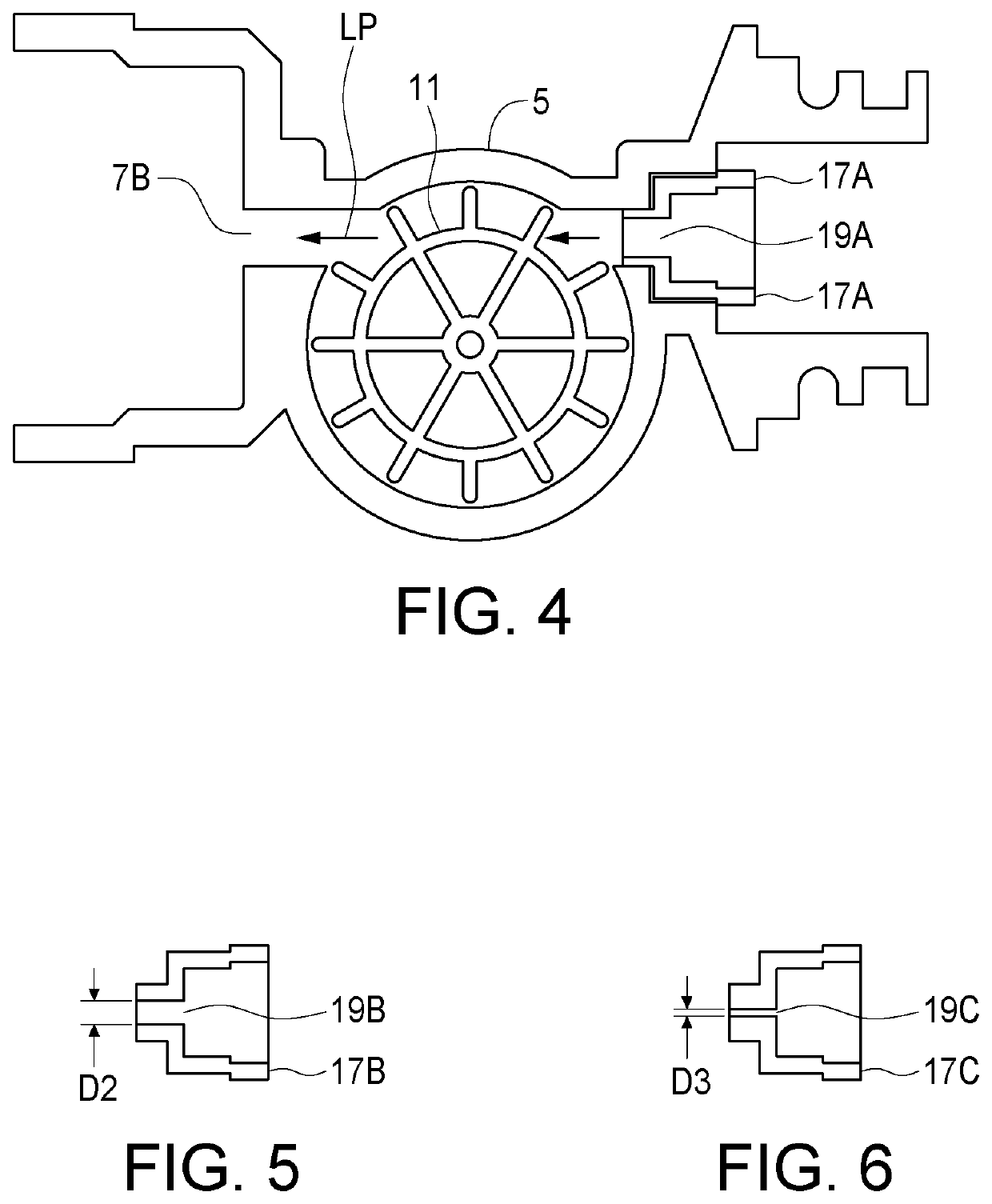
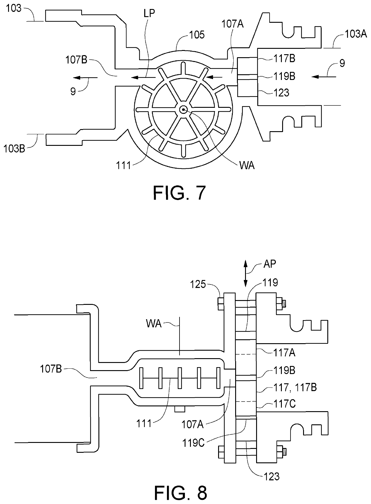
[0019]FIGS. 1-4 schematically illustrates an embodiment of a flow meter apparatus 1 of the present disclosure for measuring a rate of liquid flow in a liquid conduit 3. The apparatus 1 comprises a meter wheel housing 5 adapted at input 7A thereof for connection to an upstream end 3A of the liquid conduit 3 and adapted at an output port 7B thereof for connection to a downstream end 3B of the liquid conduit 3 such that when connected, liquid flowing in the liquid conduit 3 flows through the meter wheel housing 5 from the input port 7A to the output port 7B.

[0020]The apparatus 1 is shown with a particular configuration of releasable fittings adjacent to the input and output ports 7A, 7B which fittings will be selected to suit connection to the particular liquid conduit 3.

[0021]A meter wheel 11 is rotatably mounted in the meter wheel housing 5 about a wheel axis WA and is configured such that liquid 9 flowing from the input port 7A to the output port 7B causes the meter wheel 11 to rota...


PUM


Abstract

A flow meter has a meter wheel housing connectable in-line in a liquid conduit such that liquid flows through the meter wheel housing from an input port to an output port. Liquid flowing from the input port to the output port rotates a meter wheel mounted in the housing, and a wheel sensor measures rotational speed of the meter wheel. A first jet member defining a first orifice with a first cross-sectional area is movable into a jet operating position between the upstream end of the liquid conduit and the input port such that liquid passes through the input port into the meter wheel housing only through the first orifice. A second jet member defining a second orifice with a second cross-sectional area is movable into the jet operating position. The second cross-sectional area is less than the first cross-sectional area.

Description

RELATED APPLICATION[0001]This application is a national phase application under 35 U.S.C. § 371 of International Application No. PCT / CA2017 / 051281 filed on Oct. 27, 2017 which claims the benefit of Canadian Patent Application No 2951789 filed on Dec. 15, 2016, the contents of both of which are incorporated herein by reference in their entirety.[0002]This disclosure relates to the field of liquid material handling and in particular a flow sensor for determining liquid flow rates over a wide range.BACKGROUND[0003]Sensing and measuring the flow of liquid through various conduits is required in many industries. For example in agricultural operations herbicides, pesticides, fungicides, fertilizers, and the like are commonly sprayed in liquid form on fields or plants. Such operations are described for example in U.S. Pat. No. 9,310,233 to Schmidt and U.S. Pat. No. 8,191,795 Grimm et al., which also describe systems for determining and controlling the rates of liquid application.[0004]The ...

Claims


Application Information

Patent Timeline
Patent Type & Authority Patents(United States)
IPC IPC(8): G01F1/34G01F1/08G01F3/06
CPCG01F3/06G01F1/08G01F1/34G01F1/06
Inventor WILGER, WILFRED H.GEORGET, SEAN
Owner WILGER INDS
Why Eureka
Try Eureka