Analysis method of metal impurity content, and analysis kit of metal impurity content

A technology of metal impurities and analysis methods, applied in the direction of analyzing materials, chemical instruments and methods, testing water, etc., can solve problems such as the type and shape of metal impurities, and achieve the effect of increasing the speed of liquid flow

Pending Publication Date: 2020-10-30
ORGANO CORP
View PDF16 Cites 1 Cited by
  • Summary
  • Abstract
  • Description
  • Claims
  • Application Information

AI Technical Summary

Problems solved by technology

[0003] In addition, the types and forms of metal impurities in ultrapure water are not yet determined, but in addition to ions, they may also exist in the form of aggregated or dispersed particles

Method used


Image

  • Analysis method of metal impurity content, and analysis kit of metal impurity content
  • Analysis method of metal impurity content, and analysis kit of metal impurity content
  • Analysis method of metal impurity content, and analysis kit of metal impurity content

Examples


reference example 1

[0234]

[0235] (I process: manufacture of bulk intermediates)

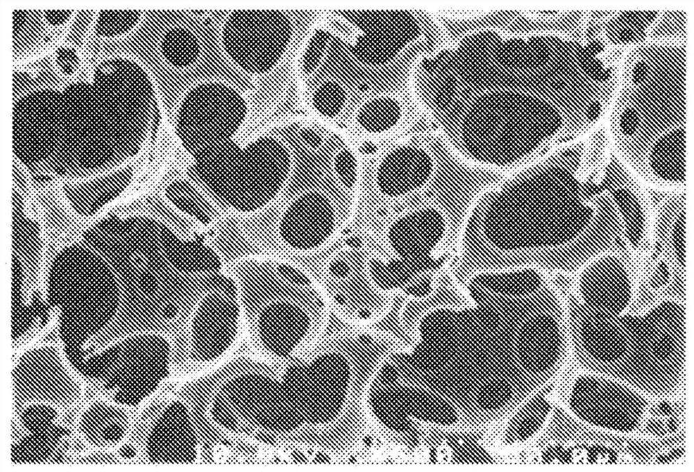
[0236] Mix 5.4 g of styrene, 0.17 g of divinylbenzene, 1.4 g of sorbitan monooleate (hereinafter abbreviated as SMO) and 0.26 g of 2,2'-azobis(isobutyronitrile) to make it uniform dissolve. Next, add this styrene / divinylbenzene / SMO / 2,2'-azobis(isobutyronitrile) mixture to 180 g of pure water, and use a planetary stirring device, namely, a vacuum stirring and defoaming mixer (EME company Production) Stirring under reduced pressure in the temperature range of 5 to 20° C. to obtain a water-in-oil emulsion. This emulsion was quickly transferred to a reaction vessel, sealed and then left to stand for polymerization at 60° C. for 24 hours. After the polymerization, the contents were taken out, extracted with methanol, and then dried under reduced pressure to produce a monolithic intermediate with a continuous macroporous structure. Observation of the internal structure of the thus obtained monolithic intermediate ...

Embodiment 1

[0253] The monolithic anion exchanger A was cut into a shape having a diameter of 10 mm×a height of 20 mm, and filled in a filling container made of PFA (tetrafluoroethylene-perfluoroalkyl vinyl ether copolymer). Next, in the filled container, under the conditions shown in Table 1, at 33mL / min. (SV=1274h -1 ) was passed through the test water 1 described later, and the test water 1 was passed through the monolithic anion exchanger A. The total flow rate of the test water 1 at this time was 100 mL.

[0254] Next, the recovered solution was measured by ICP-MS to measure the concentration of each ionic impurity element.

[0255] Next, the total amount of each ionic impurity element in the test water which was calculated from the concentration of each ionic impurity element in the test water and the total amount of liquid passing, and the concentration of each ionic impurity element in the recovered liquid were obtained. The total recovery amount of each ionic impurity element i...

Embodiment 2

[0262] The monolithic cation exchanger B was cut out in the shape shown in Table 1, and it carried out similarly to Example 1 except having passed liquid on the conditions shown in Table 1. The results are shown in Table 2.


PUM

PropertyMeasurementUnit
thicknessaaaaaaaaaa
thicknessaaaaaaaaaa
thicknessaaaaaaaaaa

Abstract

This metal impurity content analysis method is characterized by involving: an impurity capture step (1) in which, by passing water to be analyzed through a monolithic organic porous anion exchanger, metal impurities in said water are captured in the monolithic organic porous anion exchanger; an elution step (1) for passing an eluent through the monolithic organic porous anion exchanger where metalimpurities in the water to be analyzed have been captured, and, by recovering the effluent, obtaining a recovered eluent that contains metal impurities in the water to be analyzed eluted from said monolithic organic porous anion exchanger; and a measurement step (1) for measuring the content of metal impurities in the recovered eluent. By means of the present invention, a metal impurity content analysis method can be provided in which the water to be analyzed has a high rate of flow and in which the acid concentration in the eluent can be decreased.

Description

technical field [0001] The present invention relates to an analysis method and an analysis kit used in the analysis method, wherein the analysis method is used for analyzing ultrapure water and the content of metal impurities contained in trace amounts in process water in the ultrapure water manufacturing process. Background technique [0002] Ultrapure water with a very low content of ionic impurities is used in semiconductor manufacturing processes and pharmaceutical manufacturing processes. Therefore, in the production of ultrapure water used in semiconductor manufacturing processes and pharmaceutical manufacturing processes, it is important to grasp the content of trace amounts of ionic impurities contained in the ultrapure water finally produced or in the process water of the ultrapure water manufacturing process. [0003] In addition, the types and forms of metal impurities in ultrapure water are not yet determined, but in addition to ions, they may also exist in the f...

Claims


Application Information

Patent Timeline
Patent Type & Authority Applications(China)
IPC IPC(8): G01N30/00B01J20/281G01N30/02G01N33/18
CPCG01N33/18G01N33/1813B01J39/20B01J41/04B01J41/14G01N30/96B01J20/281B01J39/05
Inventor 茑野恭平
Owner ORGANO CORP
Why Eureka
Try Eureka