Electronic brake system

a technology of electronic brakes and electronic components, applied in the direction of braking systems, vehicle sub-unit features, braking components, etc., can solve the problem of not producing the deceleration desired by the driver

Active Publication Date: 2020-12-08
HL MANDO CORP
View PDF9 Cites 3 Cited by
  • Summary
  • Abstract
  • Description
  • Claims
  • Application Information

AI Technical Summary

Problems solved by technology

However, when the braking pressure is generated according to the pedal force of the brake pedal, the temperature of a disk, which varies with the temperature, the humidity, or the like during a stroke operation of the brake pedal, is not considered, thereby failing to produce a deceleration desired by the driver.

Method used


Image

  • Electronic brake system
  • Electronic brake system
  • Electronic brake system

Examples


Embodiment Construction

[0029]Hereinafter, embodiments of the present disclosure will be described in detail with reference to the accompanying drawings. The following embodiments are provided to fully convey the spirit of the present disclosure to a person having ordinary skill in the art to which the present disclosure belongs. The present disclosure is not limited to the embodiments shown herein but may be embodied in other forms. In order to make the description of the present disclosure clear, unrelated parts are not shown and, the sizes of components are exaggerated for clarity.

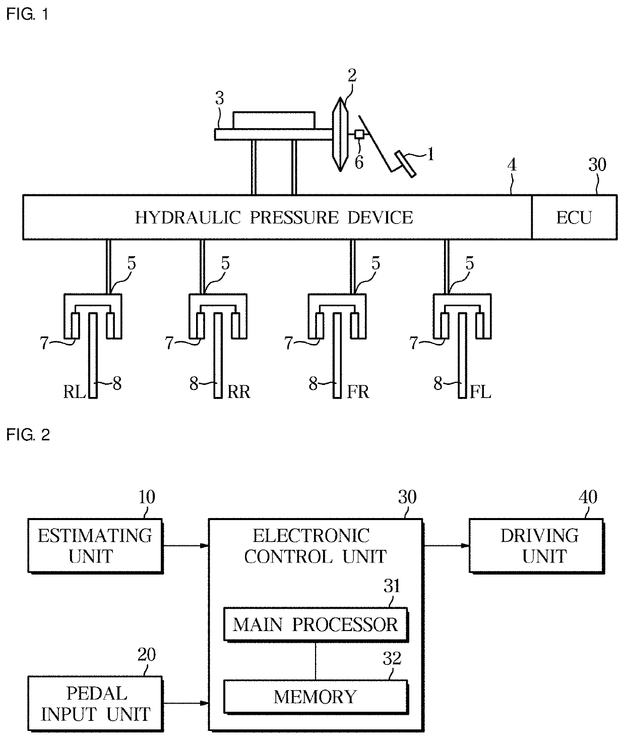
[0030]FIG. 1 is a schematic view illustrating an electronic brake system using a method of controlling an electronic brake system according to an embodiment of the present disclosure.

[0031]Referring to FIG. 1, the electronic brake system generates a braking force on the basis of a pedal force by which the driver applies a brake pedal 1 to decelerate the vehicle.

[0032]The electronic brake system boosts the pedal force by which ...


PUM


Abstract

Provided are an electronic brake system and a method of controlling the same. The electronic brake system includes a pedal input unit configured to receive a pedal force according to a driver's braking intention, an estimating unit configured to estimate a temperature and a friction coefficient of a brake disk pad, and a control unit configured to correct a braking target pressure according to the driver's braking intention on the basis of the estimated temperature and friction coefficient of the brake disk pad.

Description

CROSS-REFERENCE TO RELATED APPLICATION[0001]This application is based on and claims priority under 35 U.S.C. § 119 to Korean Patent Application No. 2017-0123984, filed on Sep. 26, 2017 in the Korean Intellectual Property Office, the disclosure of which is incorporated herein by reference.BACKGROUND1. Field[0002]The present disclosure relates to an electronic brake system, and more specifically, to an electronic brake system that generates a braking force without an error according to a driver's intention by considering the temperature of a brake disk.2. Description of the Related Art[0003]Vehicles require a brake system for braking. Recently, various types of systems have been proposed for obtaining a more powerful and stable braking force.[0004]In the case of a hybrid vehicle or an electric vehicle, a braking pressure of a friction material is compensated to correspond to a reduced regenerative braking pressure at a time of a termination of a regenerative braking.[0005]In general, ...

Claims


Application Information

Patent Timeline
Patent Type & Authority Patents(United States)
IPC IPC(8): B60L7/26B60T8/40F16D61/00B60T7/04B60T1/10B60T13/68B60T13/66B60L7/18B60T13/58B60T8/172
CPCB60T13/58B60T13/586B60L7/18B60T8/4072B60T8/4081B60L7/26B60T7/042B60T13/662B60T13/686B60T8/172F16D61/00B60T1/10B60T2270/82B60L2250/26B60T2270/404B60T2220/04B60T2270/604B60T2270/402B60T8/171B60T2270/88B60Y2400/81
Inventor LEE, EUN HA
Owner HL MANDO CORP
Why Eureka
Try Eureka