

Hose reel
a technology of hose reels and hoses, applied in the field of hose reels, can solve problems such as the inability to remove the lid, and achieve the effect of preventing the risk of injury
- Summary
- Abstract
- Description
- Claims
- Application Information
AI Technical Summary
Benefits of technology
Problems solved by technology
Method used
Image

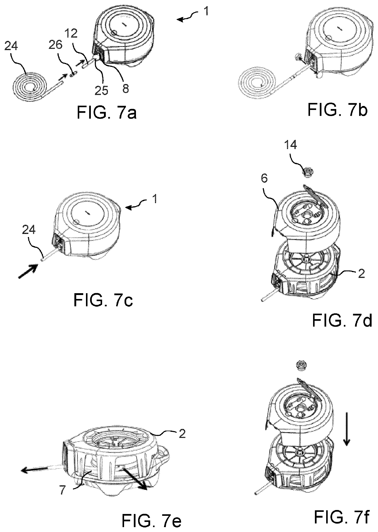
Examples
Embodiment Construction
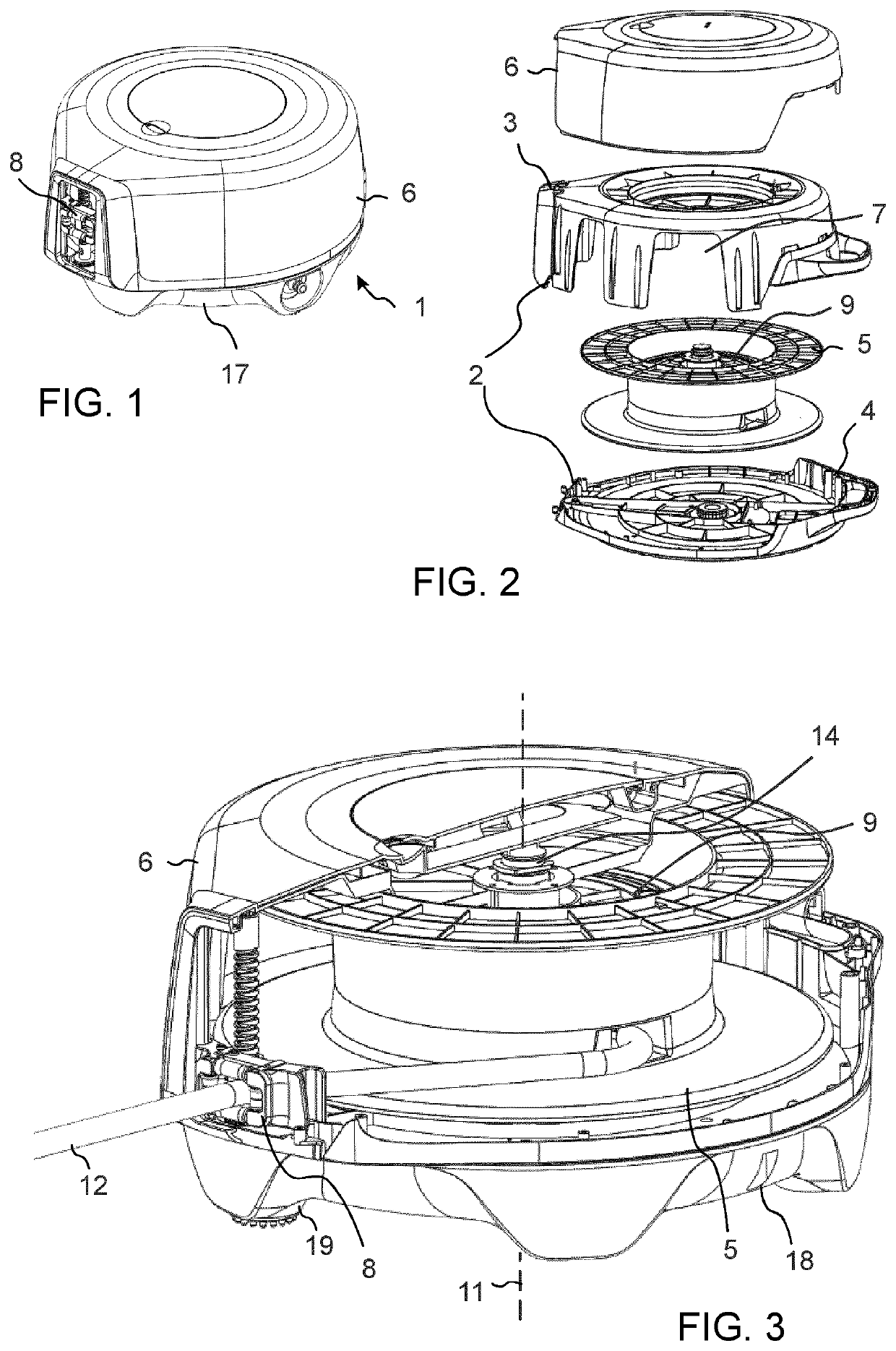
[0014]FIG. 1 illustrates a hose reel 1 from above, FIG. 2 illustrates an exploded view of a part of the hose reel 1 before assembly and FIG. 3 illustrates a partial cross section of the hose reel 1. The hose reel comprises a frame 2 which in this example comprises an upper frame part 3 and a lower frame part 4 attached to each other. A reel 5 is rotatably arranged within the frame 2 such that the reel can be accessed via side openings 7 in the frame.
[0015]In the illustrated examples it is by way of example assumed that the hose reel is a free standing hose reel provided with a reel 5 rotating around a vertical rotation axis 11, in other words an axis which is perpendicular to the base (in praxis usually the ground). However, alternatively the invention can be utilized also in a hose reel which via an attachment bracket is mounted to a wall such that the reel rotates around a horizontal rotation axis, for instance.
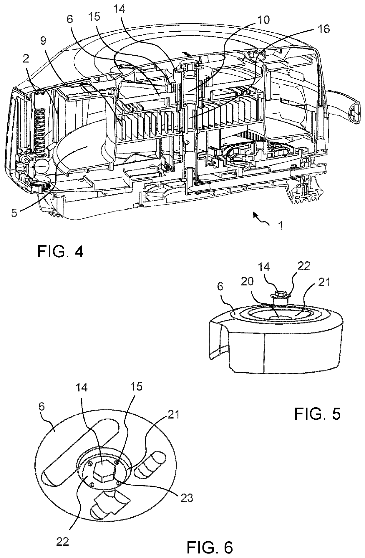
[0016]In the illustrated embodiment, the hose reel 1 is additionally p...
PUM
 Abstract
Description
Claims
Application Information