Vehicle seat

a seat and vehicle technology, applied in the field of vehicle seats, can solve the problems that the seat parts are no longer suitable for passenger transportation, and achieve the effect of increasing the loading volume of the vehicle and facilitating access

Active Publication Date: 2020-11-10
ADIENT US LLC
View PDF63 Cites 8 Cited by
  • Summary
  • Abstract
  • Description
  • Claims
  • Application Information

AI Technical Summary

Benefits of technology

[0009]The third joint (the articulated connection between the base or an adapter fixedly connected to the base and the rear rocker) can be a fitting. Since the third joint is a fitting, a cost-effective vehicle seat is provided which has only few components. There is additionally avoided a risk of injury when pivoting back the vehicle seat from an ingress position into a use position. The rear rocker has no further components, in particular no lock, which could injure a passenger of a seat row arranged behind the vehicle seat when pivoting back the rear rocker into the use position. Alternatively, the third joint can be lockable by means of a lock, in particular a rotary latch lock.
[0016]The base is preferably formed as a seat rail arrangement configured to provide a longitudinal adjustment of the vehicle seat in and counter to a longitudinal direction. As a result, the seat can be brought into an ingress position in which it is displaced forwards in the longitudinal direction with respect to the at least one use position. This particularly facilitates access to a seat row arranged behind the vehicle seat.
[0017]The vehicle seat can have a second backrest which is selectively pivotable, together with the backrest or separately from the backrest, about a backrest pivot axis defined by the fifth joint. As a result, a vehicle seat having two seating positions can be made available in which, while maintaining one of the two seating positions, and to increase the loading volume of the vehicle, the second backrest is pivotable into preferably a substantially horizontal position.

Problems solved by technology

In the case of the vehicle seats known from the prior art stated at the outset, this is not possible since pivoting of one of the backrests would automatically cause the entire seat part to be lowered, with the result that the seat part would no longer be suitable for passenger transport.

Method used


Image

  • Vehicle seat
  • Vehicle seat
  • Vehicle seat

Examples


Embodiment Construction

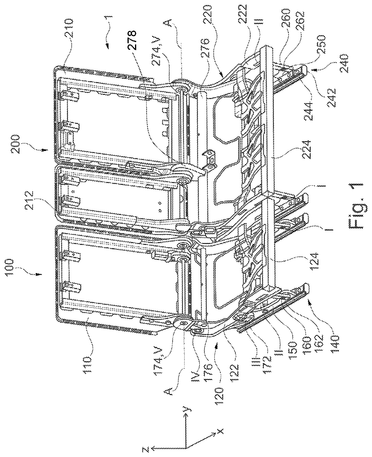
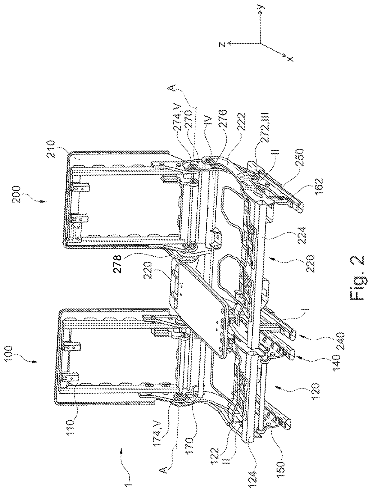
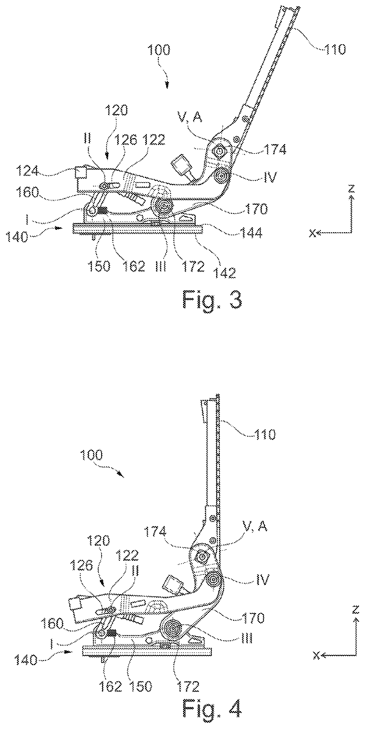
[0028]Referring to the drawings, FIGS. 1 and 2 show a seat row 1 for a vehicle, in particular motor vehicle, wherein a padding of the seat row 1 that comprises foam parts and seat covers is not illustrated. The seat row 1 is, for example, a central seat row of a vehicle, for example of a van. The seat row 1 is split in a ratio of 40% to 60% and has two vehicle seats 100, 200. A vehicle seat 100 constitutes a first exemplary embodiment of a vehicle seat according to the invention and the 40% part of the seat row 1 and offers a seating position for precisely one person. In the present case, the vehicle seat 100 provides the outer right seating position of the seat row 1. The other vehicle seat 200 constitutes a second exemplary embodiment of a vehicle seat according to the invention and the 60% part of the seat row 1 and offers a respective seating position for precisely two persons. In the present case, the vehicle seat 200 provides the central seating position and the outer left sea...


PUM


Abstract

A vehicle seat (100, 200), transferable from a use position into a non-use position, includes a seat part (120, 220), a backrest (110, 210), and a base (140, 240). A front rocker (160, 260) is articulated via a first joint (I) on the base / adapter (150, 250) fixed to the base, and is articulated via a second joint (II) on the seat part with limited displaceability. A rear rocker (170, 270) is articulated via a third joint (III) on the base / adapter fixed to the base and is articulated via a fourth joint (IV) on the seat part. A locking device (162, 262) locks the first joint, the second joint or the fourth joint to lock the front rocker about the first joint. A fifth joint (V) pivotably connects the backrest to the rear rocker. A pivoting movement of the backrest about the fifth joint can be locked.

Description

CROSS REFERENCE TO RELATED APPLICATIONS[0001]This application claims the benefit of priority under 35 U.S.C. § 119 of German Application 10 2018 112 926.2, filed May 30, 2018, the entire contents of which are incorporated herein by reference.TECHNICAL FIELD[0002]The invention relates to a vehicle seat, in particular motor vehicle seat, which can be transferred from at least one use position suitable for passenger conveyance into at least one non-use position.TECHNICAL BACKGROUND[0003]DE 10 2008 050 468 B3 discloses a vehicle seat which can be transferred from a use position suitable for passenger conveyance into a pivoted-forward non-use position, comprising: a base; a rocker which is articulated on a front foot; a seat cushion which is articulated on the rocker and has, as structure, a seat cushion carrier from which an arm projects at the rear, a joint being arranged on the end of said arm; a link which is articulated on the front foot; a rear foot which is articulated on the link...

Claims


Application Information

Patent Timeline
Patent Type & Authority Patents(United States)
IPC IPC(8): B60N2/02B60N2/06B60N2/04B60N2/75B60N2/36B60N2/10B60N2/12B60N2/30
CPCB60N2/309B60N2/3065B60N2/757B60N2/3009B60N2/30B60N2/22B60N2/36B60N2/06B60N2/3011B60N2205/35
Inventor SIVARAJ, SRINIVASAN
Owner ADIENT US LLC
Why Eureka
Try Eureka