
Solid-state image pickup apparatus, correction method, and electronic apparatus

a technology of solid-state image and pickup apparatus, applied in the direction of color television, television system, radio control device, etc., can solve the problem of reducing the performance of the af, and achieve the effect of suppressing the appearance of discomfor

Active Publication Date: 2020-12-08
SONY SEMICON SOLUTIONS CORP
View PDF22 Cites 2 Cited by
  • Summary
  • Abstract
  • Description
  • Claims
  • Application Information

AI Technical Summary

Benefits of technology

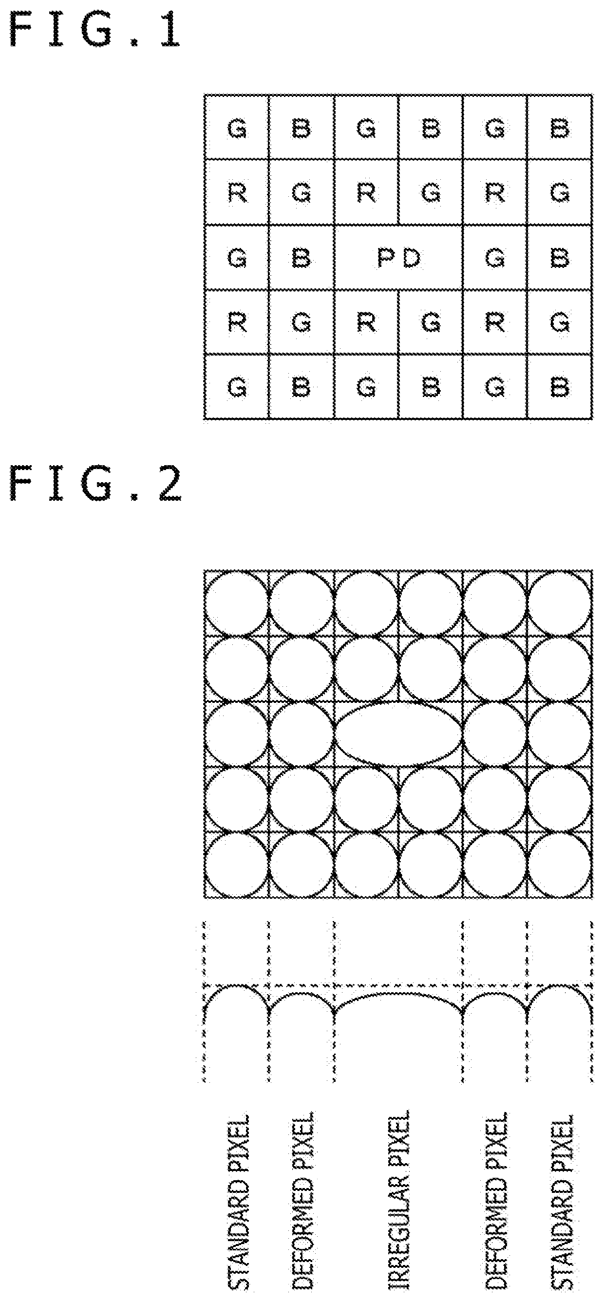
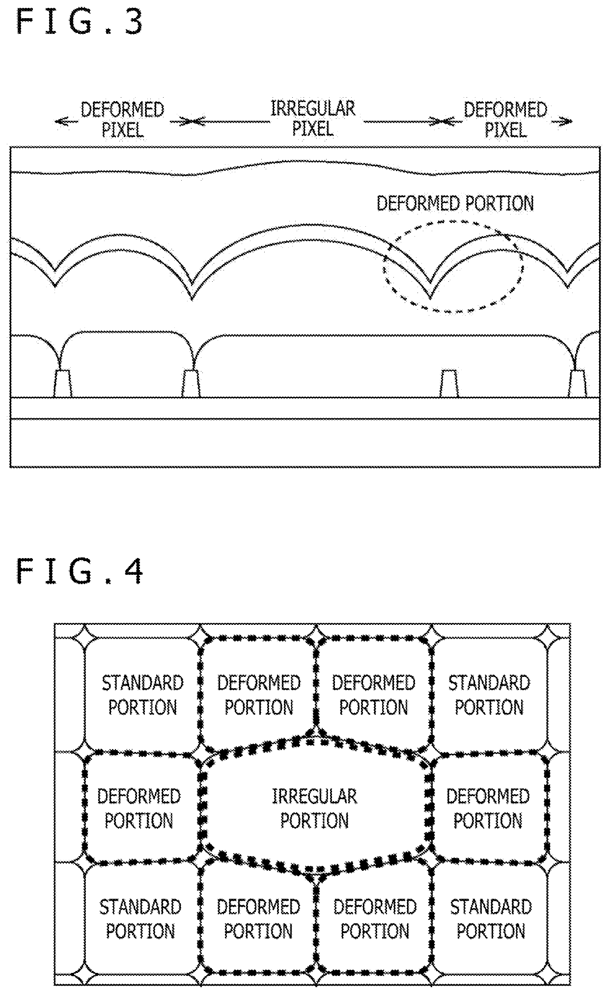
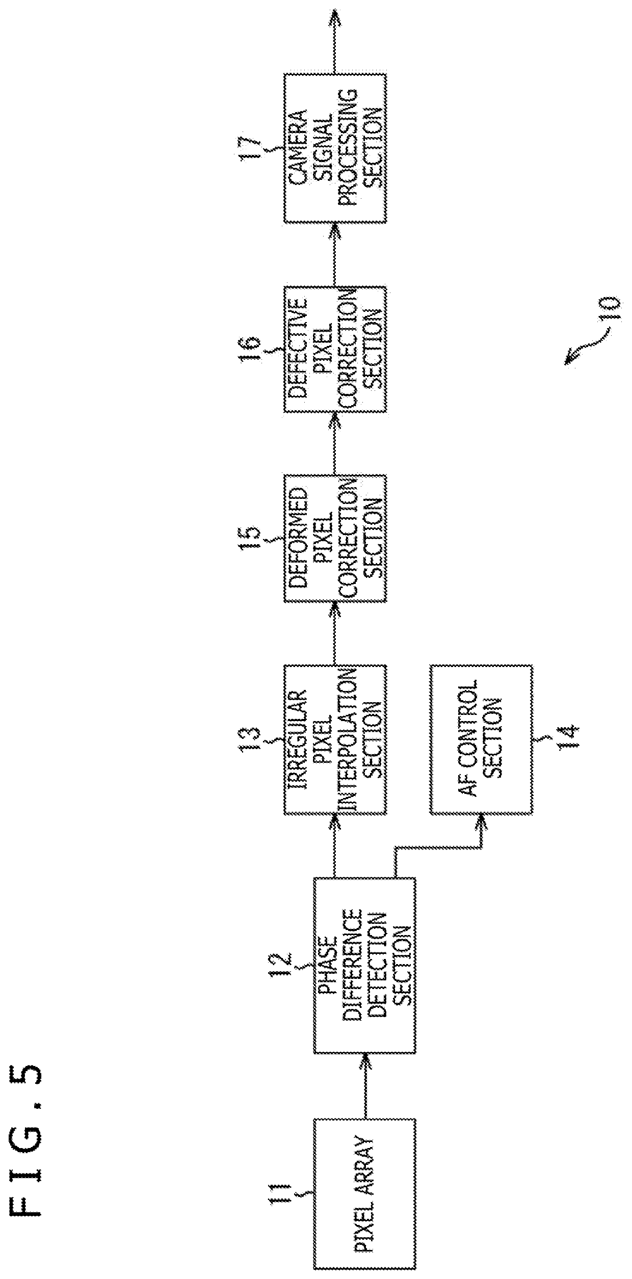
[0026]According to the first and second aspects of the present disclosure, it is possible to correct a pixel value of a second pixel in which a shape of an OCL is deformed from a standard shape, which is positioned on the periphery of a first pixel and in which the shape of the OCL is different from the standard shape.
[0027]Further, according to the first and second aspects of the present disclosure, it is possible to suppress an apparent uncomfortable feeling that may occur on an image.

Problems solved by technology

Note, however, that in a case of using the partially shaded phase difference detection pixel, since an appropriate phase difference signal is not obtained at the time of low-light intensity, an AF performance may be decreased.

Method used


Image

  • Solid-state image pickup apparatus, correction method, and electronic apparatus
  • Solid-state image pickup apparatus, correction method, and electronic apparatus
  • Solid-state image pickup apparatus, correction method, and electronic apparatus

Examples


first application example

[0095]The technology according to the present disclosure can be applied to various products. For example, the technology according to the present disclosure may be applied to an in-vivo information acquisition system of a patient using a capsule type endoscope.

[0096]FIG. 12 is a view depicting an example of a schematic configuration of an in-vivo information acquisition system 5400 to which the technology according to an embodiment of the present disclosure can be applied. Referring to FIG. 12, the in-vivo information acquisition system 5400 includes a capsule type endoscope 5401, and an external controlling apparatus 5423 which integrally controls operation of the in-vivo information acquisition system 5400. Upon inspection, the capsule type endoscope 5401 is swallowed by a patient. The capsule type endoscope 5401 has an image pickup function and a wireless communication function. For a period of time before the capsule type endoscope 5401 is discharged naturally from the patient, ...

second application example

[0109]For example, the technology according to the present disclosure may be implemented as apparatuses mounted on any type of mobile objects such as automobiles, electric vehicles, hybrid electric vehicles, motorcycles, bicycles, personal mobilities, airplanes, drones, ships, robots, construction machines, and agricultural machines (tractors).

[0110]FIG. 13 is a block diagram depicting an example of schematic configuration of a vehicle control system 7000 as an example of a mobile body control system to which the technology according to an embodiment of the present disclosure can be applied. The vehicle control system 7000 includes a plurality of electronic control units connected to each other via a communication network 7010. In the example depicted in FIG. 13, the vehicle control system 7000 includes a driving system control unit 7100, a body system control unit 7200, a battery control unit 7300, an outside-vehicle information detecting unit 7400, an in-vehicle information detect...


PUM


Abstract

The present disclosure relates to a solid-state image pickup apparatus, a correction method, and an electronic apparatus, enabled to suppress an apparent uncomfortable feeling of an image output from a solid-state image pickup apparatus in which pixels of different OCL shapes are mounted mixedly.A solid-state image pickup apparatus according to an aspect of the present disclosure includes a pixel array in which a first pixel in which an OCL (On Chip Lens) of a standard size is formed and a second pixel in which an OCL of a size different from the standard size is formed are present mixedly, and a correction section that corrects a pixel value of the first pixel that is positioned in the vicinity of the second pixel among the first pixels on the pixel array. The present disclosure can be applied to, for example, a CMOS image sensor.

Description

CROSS REFERENCE TO RELATED APPLICATIONS[0001]This application is a national stage application under 35 U.S.C. 371 and claims the benefit of PCT Application No. PCT / JP2017 / 022986 having an international filing date of 22 Jun. 2017, which designated the United States, which PCT application claimed the benefit of Japanese Patent Application No. 2016-133966 filed 6 Jul. 2016, the entire disclosures of each of which are incorporated herein by reference.TECHNICAL FIELD[0002]The present disclosure relates to a solid-state image pickup apparatus, a correction method, and an electronic apparatus, and in particular, relates to a solid-state image pickup apparatus, a correction method, and an electronic apparatus, enabled to correct a pixel value of a standard pixel for generating a color signal that is present on the periphery of a phase difference detection pixel for generating a phase difference signal.BACKGROUND ART[0003]As a method of an AF (Auto Focus) system of a digital camera etc., an...

Claims


Application Information

Patent Timeline
Patent Type & Authority Patents(United States)
IPC IPC(8): H04N5/369H04N5/365H04N5/357H01L27/146H04N5/232
CPCH01L27/14627H04N5/3572H04N5/23212H04N5/36961H01L27/14607H01L27/14605H04N5/365H04N25/61H04N25/67H04N25/704H04N23/67
Inventor TSUZUKI, TAKERUNISHIKORI, KATSUMI
Owner SONY SEMICON SOLUTIONS CORP
Learn More