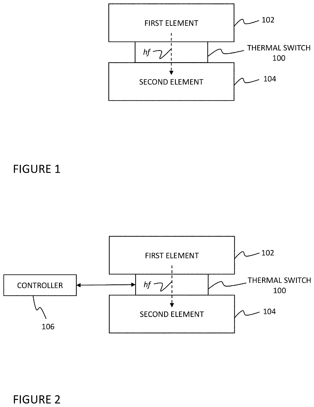
Thermal switch

a switch and thermal technology, applied in the field of thermal switches, can solve the problems of difficult limitation of efficiency, maximum heat load, rate of temperature change, etc., and achieve the effects of improving efficiency and performance, precise, rapid, and proportional control of thermal conduction

Active Publication Date: 2020-12-15
ENVERTIC THERMAL SYST LLC
View PDF112 Cites 1 Cited by
  • Summary
  • Abstract
  • Description
  • Claims
  • Application Information

AI Technical Summary

Benefits of technology

[0008]In some embodiments, thermal devices and systems incorporating features of the present invention may exhibit improved efficiency and performance. In such thermal devices and systems, precise, rapid, proportional control of thermal conduction may be provided. Devices and systems incorporating features of the present invention are highly reliable by virtue of a liquid interface, and achieve a wide range of controlled thermal conductivity, with rangeability as high as 600:1. Such devices can support structural loads and exhibit no external movement, which eases implementation.

Problems solved by technology

Controlling the temperature of machine components or workpieces is an important and common challenge in industry.
Of these three modes of heat transfer, thermal conduction is often the most difficult to control, as it is usually determined only by the thermal properties of components and the thermal couplings between components, which typically cannot be changed during operation.
An inability to control thermal conduction means commonly employed thermal control systems face limitations in efficiency, rate of temperature change, maximum heat load, or other system performance characteristics.
These limitations may be significant in thermal systems which experience fluctuating heat loads.
For example, some temperature control systems may employ a combination of modulated heating with constant cooling, an inefficient control method which limits the performance of a thermal system.

Method used


Image

  • Thermal switch
  • Thermal switch
  • Thermal switch

Examples


first embodiment

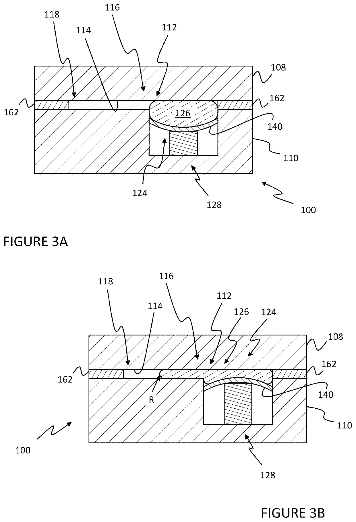
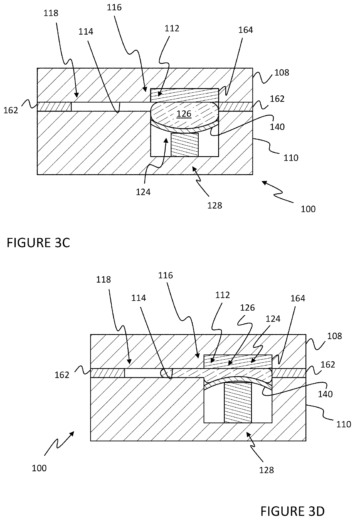
[0485]With reference to FIGS. 3A-3J, a thermal switch 100 according to a first embodiment is shown. In the illustrated embodiment, the thermal switch 100 includes a first plate 108, a second plate 110, a first reservoir 124, and an actuator 128. The actuator 128 may be an active actuator or a passive actuator. In general, an active actuator changes state in response to a control signal. Examples of active actuators include, but are not limited to, electric solenoids, pneumatic actuators, electric motors, piezoelectric actuators, MEMs actuators, electrostatic actuators and the like. In general, passive actuators change state based on an intrinsic thermal response of the actuator. Examples of passive actuators include, but are not limited to, actuators based on thermal expansion such as fluid in a piston or bellows, bimetallic elements, shape memory alloys and phase changing materials (such as melting wax in a piston). Passive actuators will generally have a fixed response (set at the...

second embodiment

[0517]With reference to FIGS. 4A-4J, a thermal switch 100 according to a second embodiment is shown. For purposes of discussion, the same reference numbers are used to refer to elements of the second embodiment of the thermal switch 100 as using in the first embodiment, where appropriate or otherwise noted.

[0518]In the illustrated embodiment, the thermal switch 100 of the second embodiment includes a first plate 108, a second plate 110, a first reservoir 124, and an actuator 128. The first plate 108 is composed from a thermally conductive material and forms a first side 148 of the thermal switch 100. For example, the first plate 108 may include a plurality of threaded apertures (not shown) and the first element 102 may be bolted or otherwise fastened to the first plate 108. It should be noted that the first element 102 may be otherwise thermally coupled to the first plate 108 including but not limited to via a thermally conductive interface or material, for example, thermal grease o...

third embodiment

[0538]With reference to FIGS. 5A-5B, a thermal switch 100 according to a third embodiment is shown. For purposes of discussion, the same reference numbers are used to refer to elements of the third embodiment of the thermal switch 100 as used in the first and second embodiments, where appropriate or otherwise noted.

[0539]Generally, the thermal switch 100 in the third embodiment is similar to the thermal switch 100 of the second embodiment, however, the actuator 128 and first reservoir 124 are located within the center of the thermal switch 100.

[0540]In the illustrated embodiment, the thermal switch 100 of the third embodiment includes a first plate 108, a second plate 110, a first reservoir 124, and an actuator 128. The first plate 108 is composed from a thermally conductive material and forms a first side 148 of the thermal switch 100.

[0541]The second plate 110 is composed from a thermally conductive material and forms a second side 150 of the thermal switch 100. In the illustrated...


PUM


Abstract

A thermal switch having an on-state and an off-state is provided. First and second plates are composed from a thermally conductive material. The first and second plates are connected to form an internal cavity having a channel defining a gap between the first and second plate. The first reservoir is coupled to the channel and contains a thermally conductive liquid. The actuator is coupled to the first reservoir and the channel and is moveable between a first state and a second state corresponding to the on-state and the off-state of the thermal switch, respectively. Thermally conductive liquid is allowed to flow from the first reservoir to the channel when the actuator is in the first state and allowed to flow from the channel to the first reservoir when the actuator is in the second state.

Description

CROSS-REFERENCE TO RELATED APPLICATION[0001]This application is a continuation of U.S. patent application Ser. No. 16 / 877,313, filed May 18, 2020, which is hereby incorporated by reference in its entirety.FIELD OF THE INVENTION[0002]The invention relates generally to thermal switches, and more particularly, to a controllable thermal switch that utilizes liquid metal to vary thermal conductivity between a heat source and a heat sink.BACKGROUND OF THE INVENTION[0003]Controlling the temperature of machine components or workpieces is an important and common challenge in industry. Components such as sensors, electronics, vessels for chemical reaction, and batteries often operate optimally at a specific temperature. Temperature dependent manufacturing processes, such as those employed in semiconductor manufacturing, rely on precise control of the temperature of a workpiece to achieve optimal results.[0004]Temperature control is generally achieved by one or both of: regulating heat generat...

Claims


Application Information

Patent Timeline
Patent Type & Authority Patents(United States)
IPC IPC(8): F28F13/00H05K7/20F25D19/00H01H37/00G05D23/02
CPCH05K7/2039F28F13/00H01H37/00F25D19/006F28F2013/006F28F2013/005F28F2013/001G05D23/02F28F2013/008
Inventor BUSCHE, MATTHEW
Owner ENVERTIC THERMAL SYST LLC
Why Eureka
Try Eureka