Image display device having ocular optical system causing images to overlap in a blending area

a technology of blending area and image display, which is applied in the field of image display devices, can solve the problems of further increase in the viewing angle hindering the reduction of a increasing the size of the optical system, so as to prevent the appearance of a boundary at a seam, increase the viewing angle, and reduce the size

Active Publication Date: 2021-01-05
SEIKO EPSON CORP
View PDF19 Cites 0 Cited by
  • Summary
  • Abstract
  • Description
  • Claims
  • Application Information

AI Technical Summary

Benefits of technology

[0004]An advantage of some aspect of the invention is to provide an image display device capable of achieving an increase in a viewing angle and a size reduction and also capable of preventing a boundary from being noticeable at a seam between separate image regions.
[0006]In the above-described ocular optical system, since the overlapping angle width in the direction orthogonal to the boundary of the blending area on the central visual field side is smaller than the overlapping angle width in the direction orthogonal to the boundary of the blending area on the peripheral visual field side, a seam between images on the central visual field side can be made less noticeable, and a seam between images on the peripheral visual field side can be narrowed to reduce overlap between optical systems. Accordingly, a boundary can be prevented from being noticeable at a seam between separate image regions, and an increase in a viewing angle and a size reduction can also be achieved.

Problems solved by technology

Furthermore, when the overlap of the image regions increases, a viewing angle of the optical system increases to achieve the viewing angle intended by design (and thus, a size of the optical system increases), and a reduction in a size of the optical system is hindered.
Furthermore, in the above-described case, a further increase in the viewing angle of the optical system is also hindered.

Method used


Image

  • Image display device having ocular optical system causing images to overlap in a blending area
  • Image display device having ocular optical system causing images to overlap in a blending area
  • Image display device having ocular optical system causing images to overlap in a blending area

Examples


embodiment

mplary Embodiment

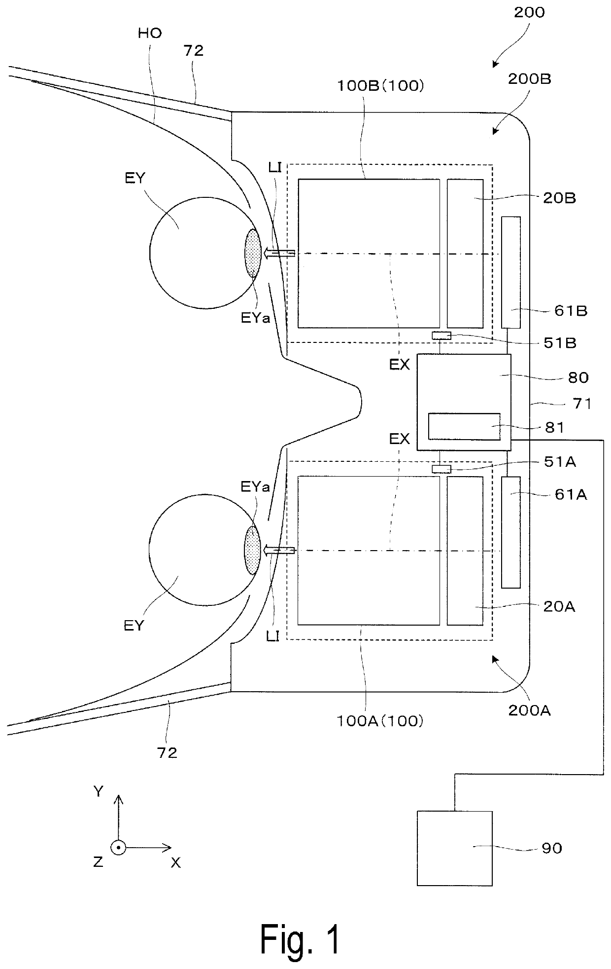
[0044]An image display device of First Exemplary Embodiment according to the invention will be described hereinafter with reference to the drawings. Note that FIG. 1 and the like each illustrate three axes X, Y, and Z of an orthogonal coordinate system, where Y corresponds to a lateral direction or a horizontal direction in which a pair of eyes of an upright observer are arranged, and Z corresponds to a vertical direction perpendicular to the lateral direction in which the eyes are arranged or a visual axis in a forward line of sight.

[0045]An image display device 200 illustrated in FIG. 1 is an eyeglass-type head-mounted display, and includes a pair of image display units 200A and 200B on left and right sides, a control circuit unit 80 configured to control display operations and the like of the image display units 200A and 200B, and an operation control unit 90 configured to receive user operations and to operate in coordination with the control circuit unit 80. Th...

second exemplary embodiment

[0107]An ocular optical system and the like according to Second Exemplary Embodiment will be described hereinafter. The ocular optical system according to this Exemplary Embodiment is a modification of the ocular optical system of First Exemplary Embodiment, and the same parts as in First Exemplary Embodiment will not be described.

[0108]FIG. 17 is an explanatory view illustrating setting of a blending area in the ocular optical system of Second Exemplary Embodiment, and corresponds to FIG. 6A. In this case, an overlapping angle width d2 in a lateral direction of a blending area BA2 between first and third optical system parts 10a and 10c is smaller than an overlapping angle width d1 in a vertical direction of a blending area BA1 between first and second optical system parts 10a and 10b. The vertical direction overlap is broadened in this manner, and thus, an overall laterally broad image can be projected by a comparatively small optical system. Note that under different circumstance...

third exemplary embodiment

[0109]An ocular optical system and the like according to Third Exemplary Embodiment will be described hereinafter. The ocular optical system according to this Exemplary Embodiment is a modification of the ocular optical system of First Exemplary Embodiment, and the same parts as in First Exemplary Embodiment will not be described.

[0110]FIG. 18 is an explanatory view illustrating setting of a blending area in the ocular optical system of Third Exemplary Embodiment. In this case, an ocular optical system 100A includes first to ninth optical system parts 10a to 10i, and an image region TI includes partial regions IA1 to IA9 aligned in a 3×3 matrix. Of blending areas BA1 to BA12 formed between the partial regions IA1 to IA9, the blending areas BA1 to BA4 closer to the center side through which a visual axis EX passes each have a width smaller than a width of each of the blending areas BA5 to BA12 located on the outer sides of the blending areas BA1 to BA4.


PUM


Abstract

An image display device includes a plurality of display elements configured to emit image light corresponding to a plurality of separate areas, and an ocular optical system configured to emit, to a position corresponding to an eye of an observer, the image light emitted from the plurality of display elements. The ocular optical system causes images to overlap with each other in a blending area including a boundary between the plurality of areas. An overlapping angle width in a direction orthogonal to the boundary of the blending area on a central visual field side is smaller than an overlapping angle width in the direction orthogonal to the boundary of the blending area on a peripheral visual field side.

Description

BACKGROUND1. Technical Field[0001]The invention relates to an image display device configured to present an image to an observer, and particularly relates to an image display device including an ocular optical system configured to emit, to an observer's eye, image light emitted from a plurality of display elements.2. Related Art[0002]There is known a head-mounted display (also called “HMD” hereinafter) including a plurality of image display means configured to display display images different from each other, and an observation optical system configured to reflect a light flux emitted from each display image by a combination reflection surface provided for each of the image display means, and to guide the light flux emitted from each of a plurality of the reflection surfaces to an observer through a single optical system (JP-A-08-240786, JP-A-2009-3128). JP-A-2009-3128 in particular also discloses combination display of original images partially overlapping with each other.[0003]How...

Claims


Application Information

Patent Timeline
Patent Type & Authority Patents(United States)
IPC IPC(8): G02B27/10G02B27/01
CPCG02B27/1066G02B27/0149G02B27/0172G02B2027/015G02B2027/0123
Inventor YAMAGUCHI, TOKITOTAKAGI, MASAYUKIMIYAO, TOSHIAKIKOMATSU, AKIRATAKEDA, TAKASHI
Owner SEIKO EPSON CORP
Why Eureka
Try Eureka