
Magnetic jewelry attachment assembly

a magnetic jewelry and assembly technology, applied in the direction of general fasteners, wristwatch straps, bracelets, etc., can solve the problem of limiting its utility, and achieve the effect of facilitating a reversible locking engagemen

Active Publication Date: 2021-01-26
PLOTNER LAURA A
View PDF15 Cites 3 Cited by
  • Summary
  • Abstract
  • Description
  • Claims
  • Application Information

AI Technical Summary

Benefits of technology

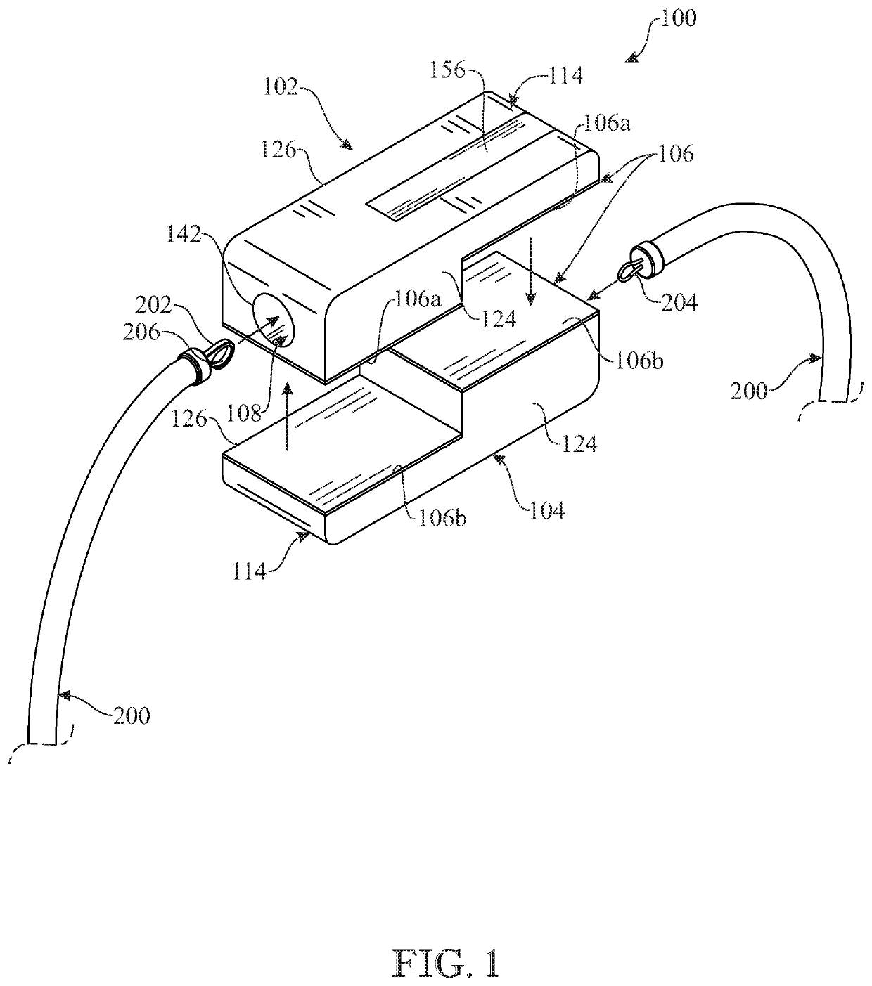
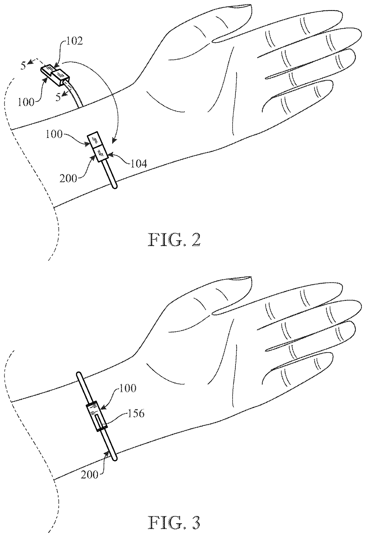
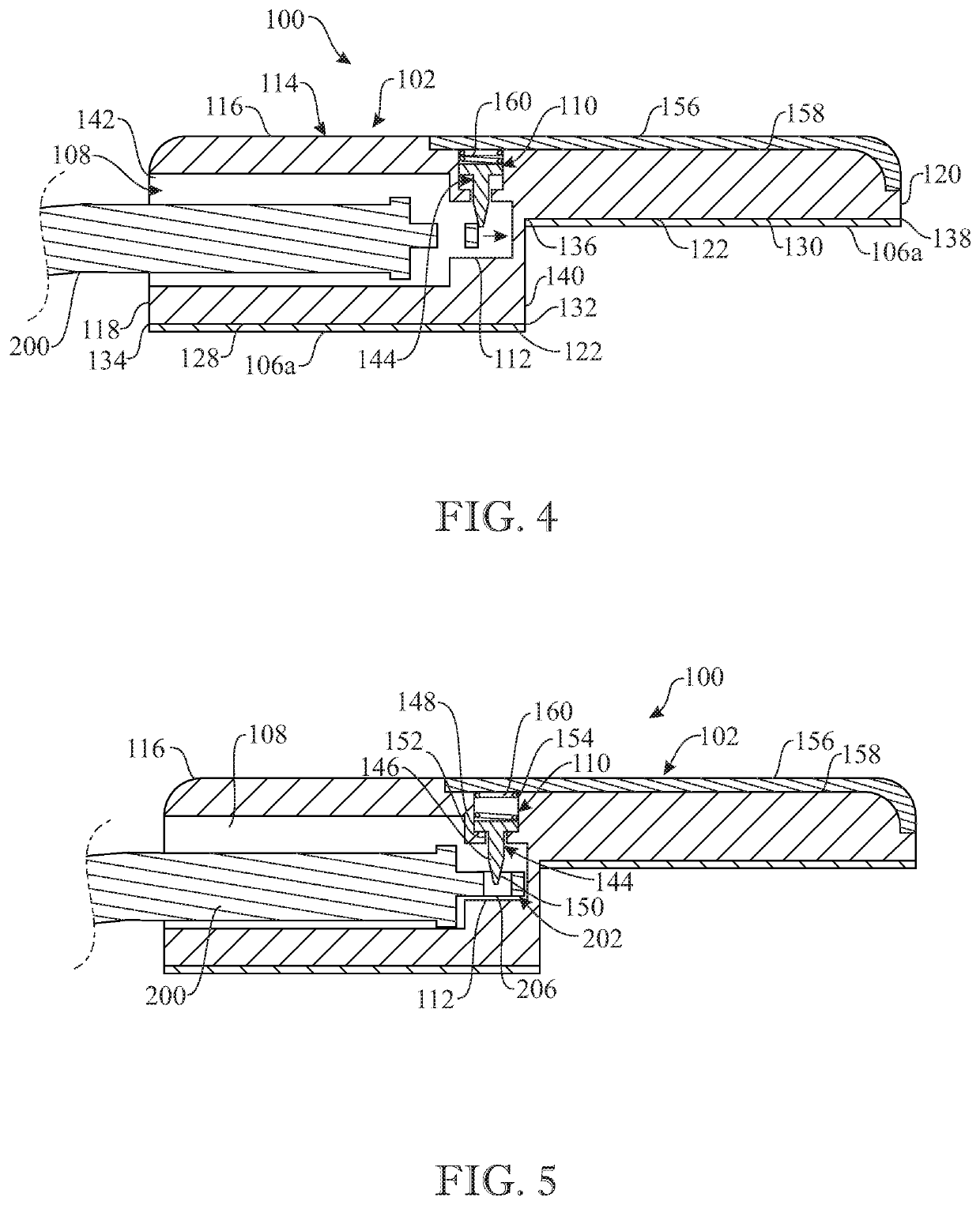
The present invention provides a jewelry attachment assembly that overcomes the deficiencies of the prior art. It includes a first case and a second case, both with splines that fit into channels in the other case to create a reversible locking engagement. The cases are equipped with magnets that create a magnetic attraction to each other. The assembly allows for easy attachment of clasps to jewelry, creating a closed loop with the assembled cases. The technical effect of this invention is to simplify the attachment process of jewelry to clasps, making it more convenient and user-friendly.

Problems solved by technology

However, the above-described approach introduces a drawback which limits its utility as a viable solution to the problem of providing a suitable magnetic jewelry clasp.

Method used


Image

  • Magnetic jewelry attachment assembly
  • Magnetic jewelry attachment assembly
  • Magnetic jewelry attachment assembly

Examples


Embodiment Construction

[0053]The following detailed description is merely exemplary in nature and is not intended to limit the described embodiments or the application and uses of the described embodiments. As used herein, the word “exemplary” or “illustrative” means “serving as an example, instance, or illustration.” Any implementation described herein as “exemplary” or “illustrative” is not necessarily to be construed as preferred or advantageous over other implementations. All of the implementations described below are exemplary implementations provided to enable persons skilled in the art to make or use the embodiments of the disclosure and are not intended to limit the scope of the disclosure, which is defined by the claims. For purposes of description herein, the terms “upper”, “lower”, “left”, “rear”, “right”, “front”, “vertical”, “horizontal”, and derivatives thereof shall relate to the invention as oriented in FIG. 1. Furthermore, there is no intention to be bound by any expressed or implied theo...


PUM


Abstract

A jewelry attachment assembly includes a pair of cylindrical cases. One case has a male section including an annular flange with a pair of diametrically opposing radial splines situated on its periphery. The other case has a female section including a hollow sleeve with a shell. The sleeve includes a pair of diametrically opposite channels formed in the shell. Each channel includes an axially extending slot and an adjoining circumferentially extending slot. During assembly, the male section of one case is joined to the female section of the other case by registration of the pair of splines within the pair of circumferential slots by first guiding the splines through the axial slots, then guiding the splines through the circumferential slots. A pair of opposite polarity magnets are housed in the cases and disposed in adjacent relationship to promote magnetic coupling of the cases.

Description

CROSS REFERENCE(S) TO RELATED APPLICATION(S)[0001]This U.S. non-provisional patent application claims the benefit of U.S. provisional patent application No. 62 / 459,704, filed Feb. 16, 2017, which is hereby incorporated-by-reference herein its entirety.FIELD OF THE INVENTION[0002]The present invention relates to fastening devices for jewelry, such as bracelets and necklaces, and, more particularly, is concerned with a magnetic jewelry attachment assembly.BACKGROUND OF THE INVENTION[0003]Jewelry, such as bracelets and necklaces, typically include fastening devices, such as clasps, that affix one end of an open loop to another to close the loop. Elderly persons, as well as many others, with vision or dexterity issues, have a problem engaging and disengaging many jewelry clasps and thus have a particular need for clasps that will make an item of jewelry easier to put on and take off and still have an aesthetically pleasing appearance and be secure when worn.[0004]Jewelry clasps incorpor...

Claims


Application Information

Patent Timeline
Patent Type & Authority Patents(United States)
IPC IPC(8): A44C5/20A44C5/18
CPCA44C5/2057A44C5/185A44C5/2071A44D2200/10A44D2203/00A44D2200/12
Inventor PLOTNER, LAURA A.
Owner PLOTNER LAURA A
Learn More